In this tutorial, we are going to interface the HC-SR04 Ultrasonic Sensor with the ARIES v2 Board. An ultrasonic sensor is an electronic device that measures the distance of a target object by emitting ultrasonic sound waves and converts the reflected sound into an electrical signal. Ultrasonic waves travel faster than the speed of audible sound (i.e. the sound that humans can hear). The Ultrasonic sensors have two main components: the transmitter (which emits the sound using piezoelectric crystals) and the receiver (which encounters the sound after it has traveled to and from the target).
Ultrasonic sensing is one of the best ways to sense proximity and detect levels with high reliability.
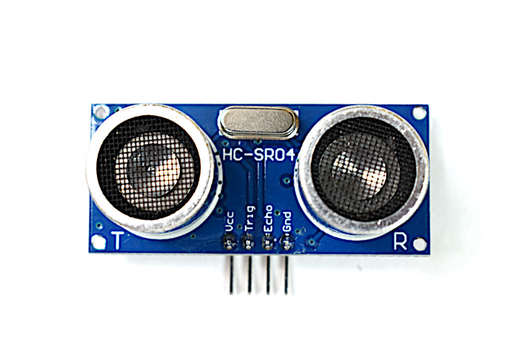
HC-SR04
This is the HC-SR04 ultrasonic distance sensor. This economical sensor provides 2cm to 400cm of non-contact measurement functionality with a ranging accuracy that can reach up to 3mm. Each HC-SR04 module includes an ultrasonic transmitter, a receiver, and a control circuit.
The transmitters emit a high-frequency ultrasonic sound, which bounces off any nearby solid objects, and the receiver listens for any return echo. That echo is then processed by the control circuit to calculate the time difference between the signal being transmitted and received. This time can subsequently be used, along with some clever math, to calculate the distance between the sensor and the reflecting object!
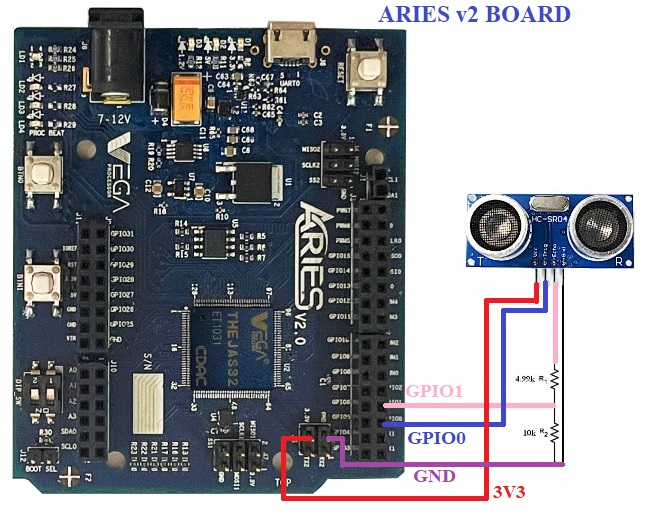
Circuit Diagram
The ultrasonic sensor is composed of 4 pins. Connect VCC and GND to +5V and GND respectively. Then connect Trig to GPIO0 and Echo to a voltage divider as shown in the figure below and take output from the voltage divider to GPIO1 of ARIES v2 Board. The voltage divider is used , in order to reduce the input voltage from echo pin to a range of 3.3V.
Now, for powering up and programming the code into the ARIES v2 Board, we have to connect a micro USB type B (common data cable, used for mobile charging and data transfer) in the UART0 port of the ARIES v2 Board, to a Laptop/Desktop/PC with preinstalled VEGA SDK and Toolchain.
| Ultrasonic Sensor | ARIES v2 Board |
| VCC | 5V |
| GND | GND |
| Trigger | GPIO0 |
| Echo | R1 *** |
Procedure
After setting up the toolchain and SDK path environments are ready, build the example program for the ultrasonic sensor module by:
cd vega-sdk/examples/gpio/ultrasound_sensor_pgmmake clean command to clean the executable :
make cleanthen use make command to build it.
makeNow, we can transfer the built program to the board, before transfer please ensure that you have connected UART0 connector of the board to the PC.
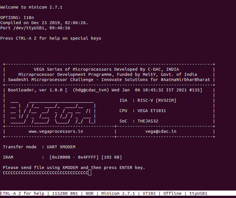
Open a new terminal and execute the following command.
minicom ariesNow you can see the minicom terminal opened and the board uart terminal is ready.
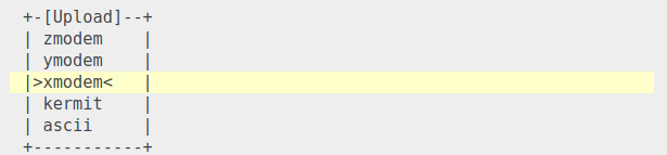
Use CTRL+A S to enter file sending menu and select xmodem by pressing Enter.
In the next window, with the space bar select the ultrasound_sensor_pgm.bin file to be transferred, by pressing Enter, the transfer process starts.
Wait until the process is completed. The screen should display how much data has been transferred.
After completing transfer the Program will start to execute.
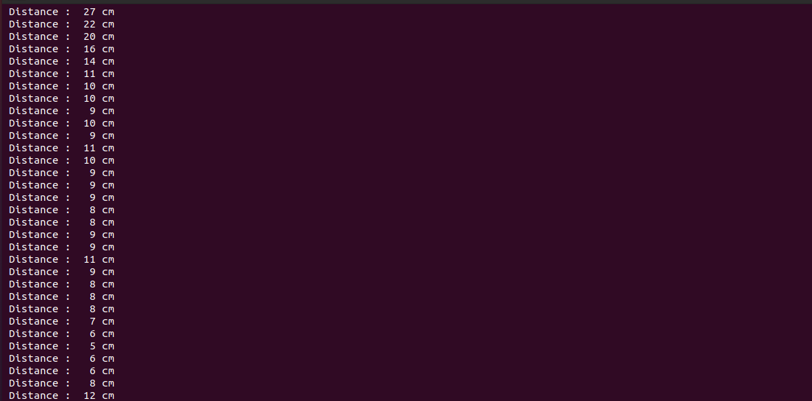
The output is displayed in minicom UART terminal:
for additional information:
https://cdn.sparkfun.com/datasheets/Sensors/Proximity/HCSR04.pdf