Now we are going to learn how we can interface the ESP-01 WiFi Module with ARIES v3 Board. The ESP-01 is a low-cost Wi-Fi microchip, with a full TCP/IP stack and microcontroller capability. This small module allows microcontrollers to connect to a Wi-Fi network and make simple TCP/IP connections using Hayes-style commands.
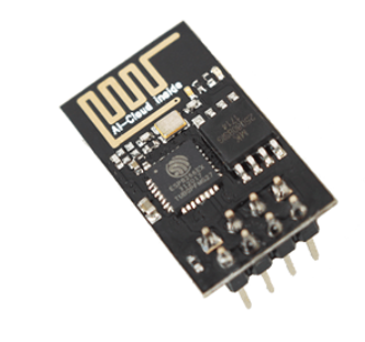
ESP 01 Wi-Fi Module
ESP 01 is a highly integrated chip designed for the needs of a new connected world. It offers a complete and self-contained Wi-Fi networking solution allowing it to either host the application or to offload all Wi-Fi networking functions from another application processor. ESP 01 has powerful on-board processing and storage capabilities that allow it to be integrated with the sensors and other application-specific devices through its GPIOs with minimal development up-front and minimal loading during runtime.
Its high degree of on-chip integration allows for minimal external circuitry. It is designed to occupy a minimal PCB area.
Prerequisites
- Windows 10 or above/Linux (64 bit)
- Arduino IDE
- VEGA ARIES Board support package
Components Required
- ARIES v3.0 Board
- USB type C to USB type A cable
- ESP 01 Wi-Fi module
- Jumper Wires
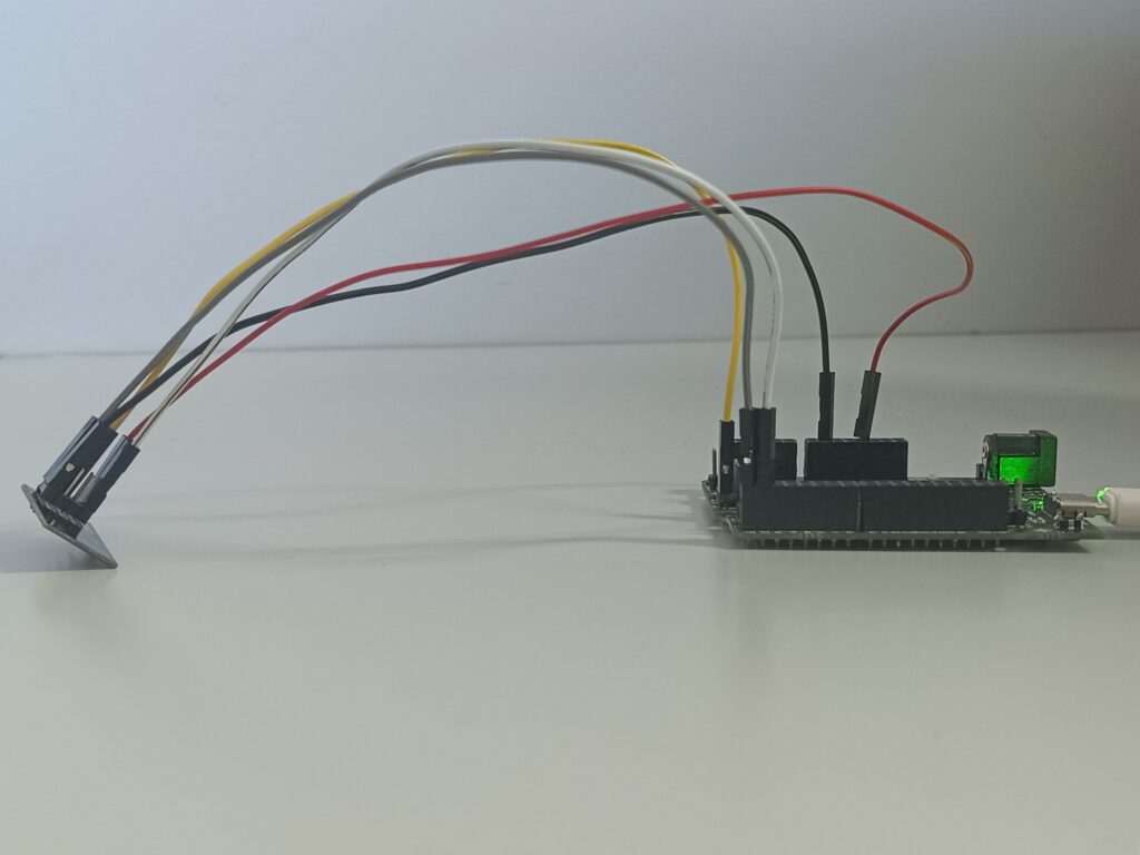
Circuit Diagram
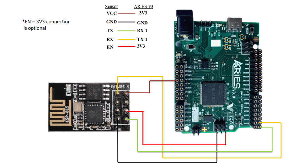
| ESP 01 WiFi Module | ARIES v3 Board |
| VCC | +3V3 |
| GND | GND |
| RXD | TX1 |
| TXD | RX1 |
| *EN | +3V3 |
*Note: Connection of EN pin in ESP to VCC (3V3) of ARIES board is optional.
Procedure
We have to configure the Adafruit IO cloud server before uploading the program to ARIES microcontroller.
Follow the below steps for configuring Adafruit IoT cloud platform
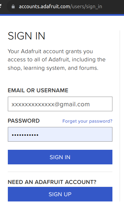
- SIGN UP on Adafruit from Adafruit IO if you doesn’t have an account. If you have Adafruit account use SIGN IN option and login with your credentials.
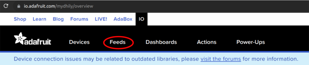
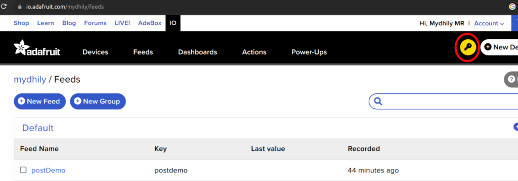
- Click on feeds menu
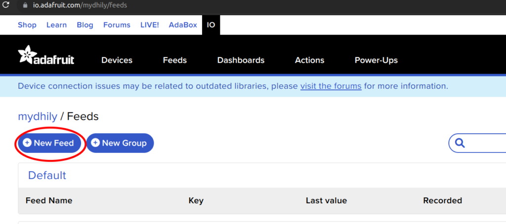
- Once the feed menu is opened, Click on New feed
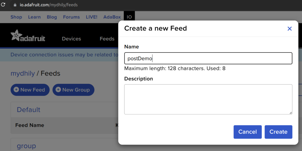
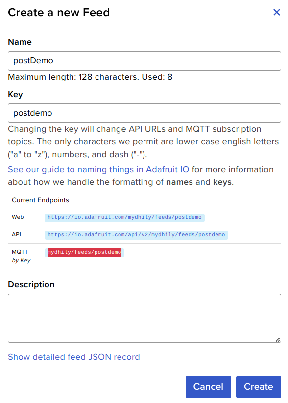
- Create a new feed by giving any feed name. Here we have used “postDemo” as the feed name. You can give any feed name and Click on Create
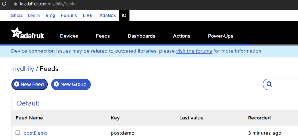
- Now you can see the feed has been created as follows.
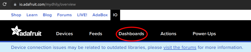
- Now click on Dashboards menu
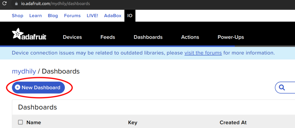
- Click on New Dashboard for creating a dashboard
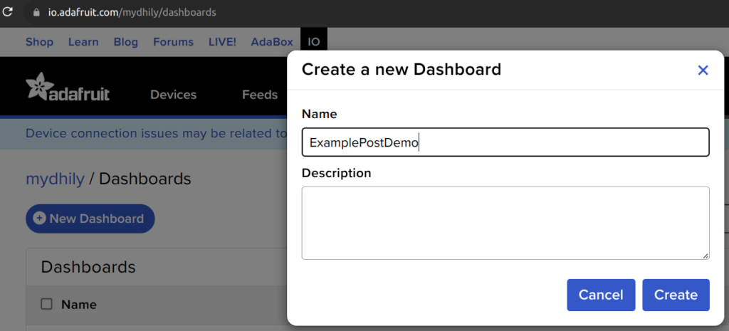
- Give any Dashboard name you like. Here we have given “ExamplePostDemo” as dashboard name and click on Create
- Now you can see the dashboard has been created as follows.
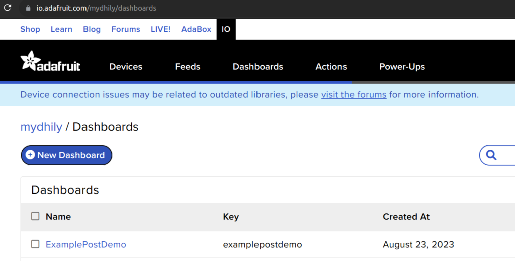
- Click on the Dashboard name you created, to open the dashboard.
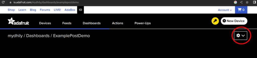
- Once you enter inside the dashboard you created, you can see a black page as follows. Click on the gear icon on the top right
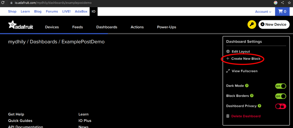
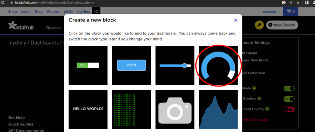
- This will open up a menu as shown in the below figure. Click on Create New Block
- You can see the available blocks to display the data. Here we will be using the Gauge block to display the random data coming from the ARIES micro-controller. You can also use line chart or text display or any other blocks based on your requirements.
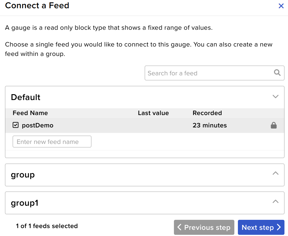
- In the next step, Tick Mark the checkbox to link your feed with the dashboard and click on NEXT STEP
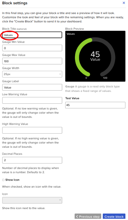
- Give a block title for your selected block. Remaining fields are optional and click on Create Block.
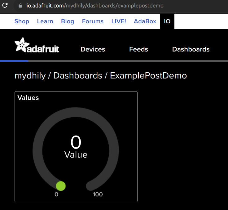
- Now the block has been created. The data from the sensor will be displayed inside this block you created now.
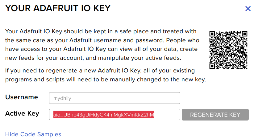
- Click on the yellow key icon to Copy the Adafruit API key (Active Key) to replace the key in the Arduino code.
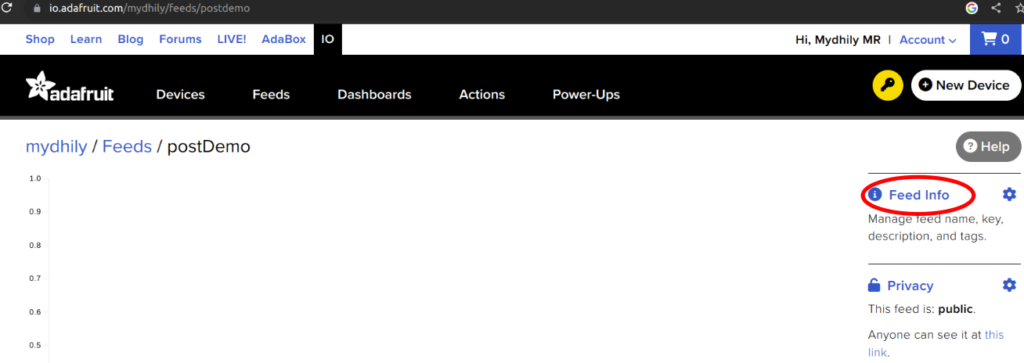
- Click on feed -> Feed info. Copy the MQTT key to replace in the URL portion in the Arduino code
Now you need to change the Credentials in Arduino program
Open and set up the Arduino IDE as described in Getting Started with ARIES v3.0.
- Connect Aries board to your computer via the USB port of a Laptop/Desktop/PC. We have to use a USB type C to USB type A cable. The cable should be connected to UART-0 port of the ARIES v3 board, and the Laptop/Desktop/PC should be preinstalled with Arduino IDE and VEGA ARIES boards of latest version.
- After connecting ARIES v3 board to your computer, Make sure you have selected ARIES v3 Board from Tools -> Board -> VEGA Processor: ARIES Boards -> ARIES v3
- Select Flash Mode -> Enabled
- Select Programmer as VEGA FLASHER from Tools -> Programmer -> VEGA FLASHER
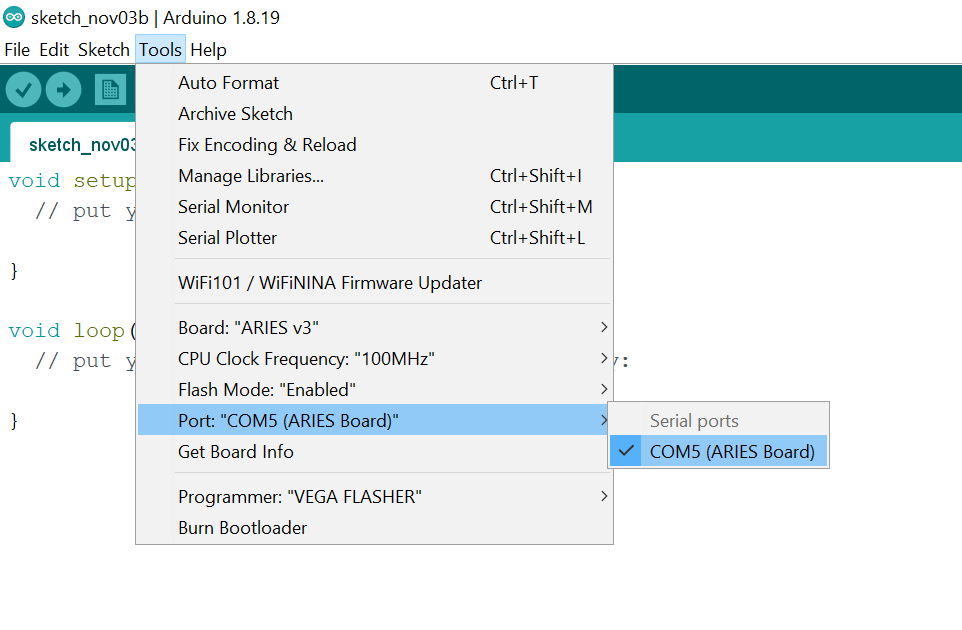
- Also select appropriate port from Tools -> Port -> COM* (ARIES Board)
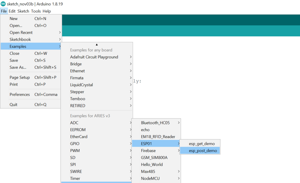
- Now, Open Files -> Examples -> Under Examples for ARIES v3 -> UART-> ESP01 -> esp_post_demo
- Change the credentials on the code as shown in the image
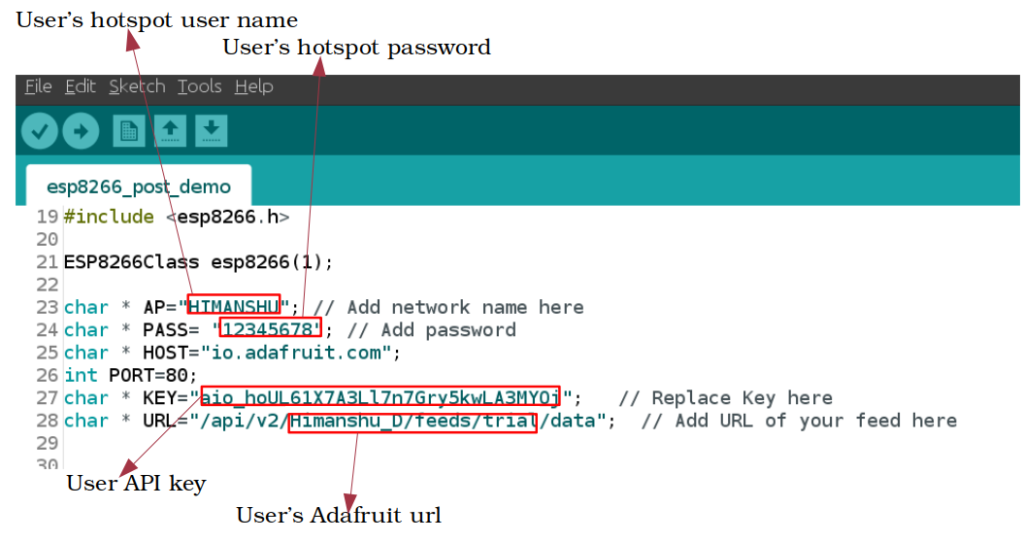
Once the hotspot name, hotspot password,KEY and URL has been replaced with your’s, the procedure is completed.
Finally, Upload the code to ARIES v3 Board.
Output
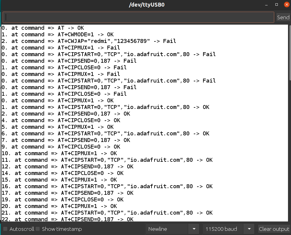
Now, when you open your Serial Monitor in the Arduino IDE , you can see the AT commands. The first AT command (AT -> OK) indicates that the circuit connections are correct. If first AT command itself is fail (AT -> Fail) it means your connections between Wi-Fi module and ARIES board are wrong, so you need to make the correct connections and upload the code once again. If you have done all steps correctly, within a few seconds all the AT commands will become OK in the serial monitor.
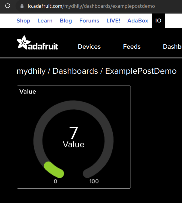
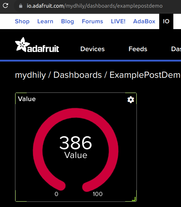
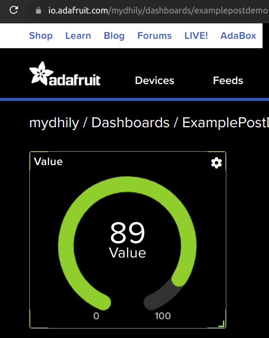
Once all the AT commands are OK, then the data will automatically sent to the Adafruit cloud platform. You can open the dashboard you created in Adafruit to view the real time data in Adafruit server as shown in the below images. In the example program given, we are sending random data using the random function available in the Arduino program. So the random values will be displayed in the Adafruit cloud server as shown.