In this tutorial, we will see how we can interface RC-522 RFID module to Aries v2.0 Board.
Radio-Frequency Identification(RFID)
RFID stands for Radio-Frequency Identification. RFID uses electromagnetic fields to automatically identify and track tags attached to objects. The tags contain electronically stored information.
An RFID system consists of a tiny radio transponder, a radio receiver, and a transmitter. When triggered by an electromagnetic interrogation pulse from a nearby RFID reader device, the tag transmits digital data, usually an identifying inventory number, back to the reader. This number can be used to track inventory goods.
There are two types of tag:
1)Passive tags – It collects the energy from a nearby RFID reader’s interrogating radio waves.
2) Active tags – It has a local power source (such as a battery) and may operate hundreds of meters from the RFID reader.
Unlike a barcode, the tags don’t need to be within the line of sight of the reader, so it may be embedded in the tracked object.
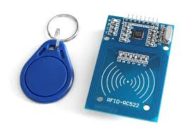
The RC522 RFID Reader module is designed to create a 13.56MHz electromagnetic field that it uses to communicate with the RFID tags (ISO 14443A standard tags). The reader module can communicate with a micro-controller over a 4-pin Serial Peripheral Interface (SPI).
Circuit Diagram:
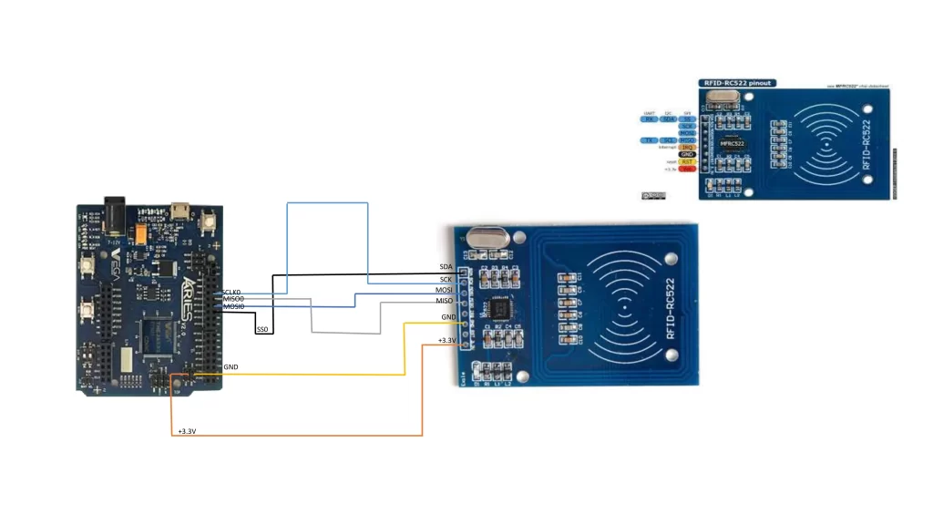
Connections:
| RC522 Module | ARIES V2 board |
| VCC | +3.3V |
| SDA | SS0 |
| SCK | SCLK0 |
| MOSI | MOSI0 |
| MISO | MISO0 |
| GND | GND |
Now, for powering up the ARIES v2 board via USB port of a Laptop/Desktop/PC and burning the code into the ARIES v2 board, we have to use a micro USB type B to USB type A cable. The cable should be connected to UART0 port of the ARIES v2 board, and the Laptop/Desktop/PC should be preinstalled with VEGA SDK and Toolchain.
Procedure:
After setting up the toolchain and SDK path environments, clean the executable using make clean command.
cd examples/spi/rc522_rfid_demo/make cleanBuild the example program for RFID-RC522 sensor by using make command
make Before transferring the built program to board, ensure that you have connected the UART0 connector of the board to the PC.
Open a new terminal, execute the following command
sudo minicom ariesNow you can see the minicom terminal opened and the board UART terminal is ready.
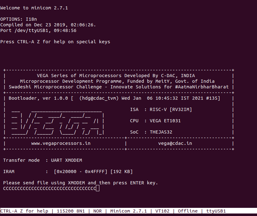
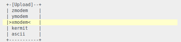
Press CTRL+A and then press S to enter file sending menu and select xmodem by pressing Enter.
In the next window, with Space bar select the rc522_rfid_demo.bin file to be transferred. By pressing Enter, transfer process starts.
Wait until the process is completed. The screen should display how much data has been transferred.
After completing transfer the program will start to execute.
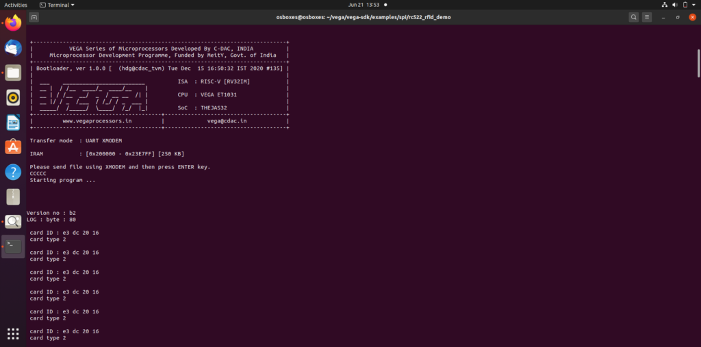
Output:
When we bring an RFID Card near to the RFID-RC522 Sensor it shows respective Card Id and Card type as shown below: