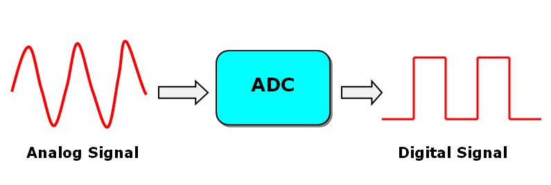
Analog-to-digital conversion (ADC) is necessary because, while embedded systems deal with digital values, their surroundings typically involve many analog signals such as temperature, speed, pressure, the output of a microphone, etc. They all need to be converted into digital data before being processed by the microcontroller. In this tutorial, we will learn how to get ADC values through the ARIES v2 Board.
Need of Analog to Digital Converter ??
When we build projects using a Microcontroller, we normally would connect different sensors to obtain information regarding the physical world and do some processing based on that information. So, when talking about communication, there are two types of signals that we often come across:
- Analog Signals
- Digital Signals
Analog signals are a type of continuous signal which are time-varying. Most of the environmental sensors such as temperature, light, pressure, and sound sensors communicate with microcontrollers using analog signals. These analog sensors output values in a specific range based on what the sensors are sensing.
Digital signals are a type of discrete signal which are time-varying. The data is carried in the form of binary in a digital signal. This means it can either carry a “0” or a “1”. If you think about a switch, it sends out digital signals when pressing it to turn on while transmitting as a “1” and when pressed again to turn off while transmitting as a “0”.
When you need to use analog sensors and communicate with a microcontroller, it is not possible for the microcontroller to directly understand these analog signals because microcontrollers only understand digital signals which are formed by 1’s and 0’s. Therefore, this kind of system needs an intermediate device that could convert the analog signals from these sensors to digital signals in order for the microcontroller to understand these signals.
For the demonstration, we use a Potentiometer and vary its value from Minimum to maximum and vice versa. For a better understanding, we have scaled the values to the corresponding output voltage.
Circuit Diagram
The Potentiometer has three pins. Connect +3.3V and GND of ARIES v2 board to the terminal pins of the potentiometer. Then connect the middle pin of the potentiometer to the Analog pin A0 of the ARIES v2 Board.
Now, for powering up the ARIES v2 board via USB port of a Laptop/Desktop/PC and burning the code into the ARIES v2 board, we have to use a micro USB type B to USB type A cable. The cable should be connected to UART0 port of the ARIES v2 board, and the Laptop/Desktop/PC should be preinstalled with VEGA SDK and Toolchain.
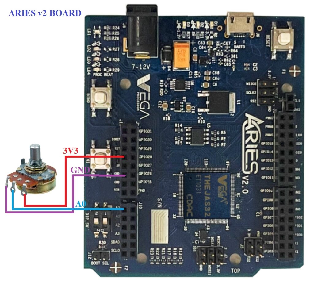
| ADC demo | ARIES v2 Board |
| VCC | +3.3V |
| GND | GND |
| Analog out (middle pin) | A0 |
Procedure
After setting up the toolchain and SDK path environments are ready, build the example program for ADC demo by :
cd vega-sdk/examples/adc/adc_democlean command to clean the executable :
make cleanthen use make command to build it.
makeNow, we can transfer the built program to the board, before transfer please ensure that you have connected the board UART connector to the PC.
Open a new terminal and execute the following command.
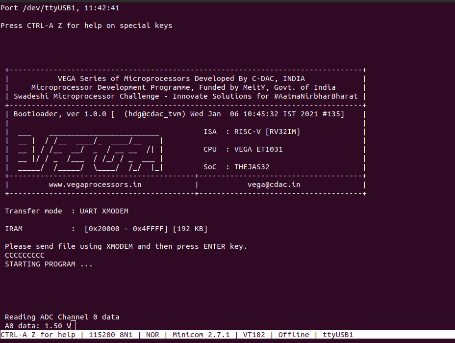
sudo minicom ariesNow you can see the minicom terminal opened and the board UART terminal is ready.
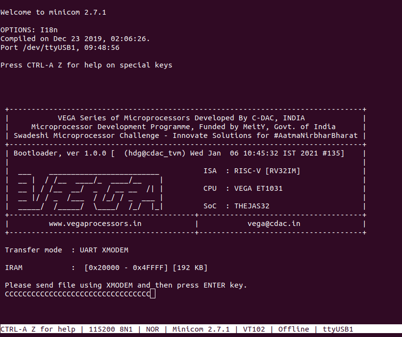
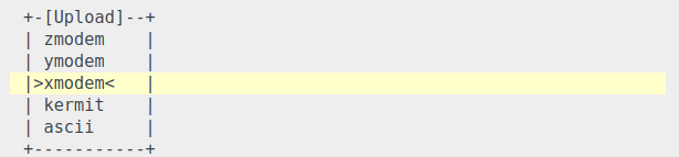
Use CTRL+A S to enter file sending menu and select xmodem by pressing Enter.
In the next window, with the space bar select the adc_demo.bin file to be transferred, by pressing Enter, the transfer process starts.
Wait until the process is completed. The screen should display how much data has been transferred.
After completing transfer the Program will start to execute.
The output is displayed in minicom UART terminal: