This example shows you how to read an analog input on analog pin 0, convert the values from analogRead() into voltage, and print it out to the serial monitor of the Arduino Software (IDE).
Prerequisites
- Windows 10 or above/Linux (64 bit)
- Arduino IDE
- VEGA ARIES Board support package
Components Required
- ARIES v3.0 Board
- Jumper Wires
- USB type C to USB type A cable
Circuit Diagram:
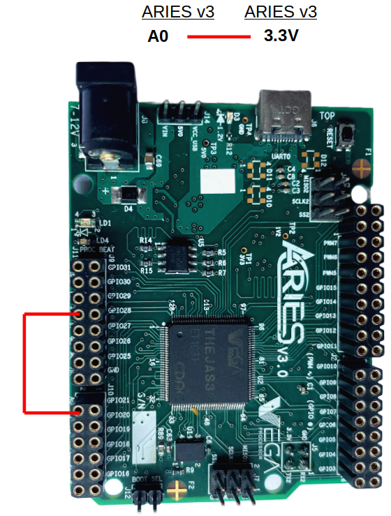
Diagram for M-M wire connected to VCC (3.3V)
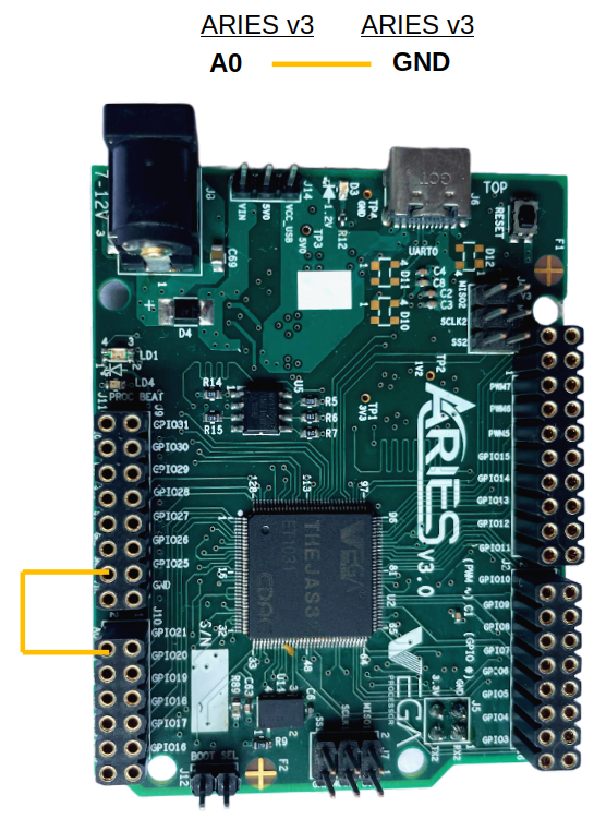
Diagram for M-M wire connected to GND (0 V)
The above circuit reads an analog input on pin A0, converts it to voltage, and prints the result to the Serial Monitor. Graphical representation is available using Serial Plotter (Tools > Serial Plotter menu). Using a male-male jumper wire, Attach one end of the jumper wire to pin A0, and the other end of jumper wire to +3.3V or ground.
| M-M wire | ARIES v3.0 Board |
| One end | A0 |
| Other end | 3V3 / GND |
Once we are done with the connections, let’s power up the ARIES v3 board via the USB port of a Laptop/Desktop/PC and burning the code into the ARIES v3 board, we have to use a USB type C to USB type A cable. The cable should be connected to UART-0 port of the ARIES v3 board, and the Laptop/Desktop/PC should be preinstalled with Arduino IDE and VEGA ARIES boards of latest version.
Procedure
Open and set up the Arduino IDE as described in Getting Started with ARIES v3.0.
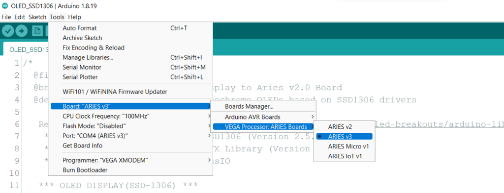
- Make sure you have selected ARIES v3 Board from Tools -> Board -> VEGA Processor: ARIES Boards -> ARIES v3
- Select Programmer as VEGA XMODEM from Tools -> Programmer -> VEGA XMODEM
- Also select appropriate port from Tools -> Port -> COM* (ARIES v3)
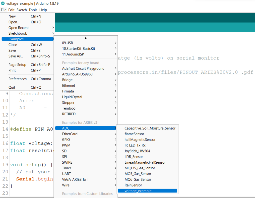
Now, Open Files -> Examples -> Under Examples for ARIES v3 -> ADC -> voltage_example
Finally, let’s Upload the code to ARIES v3 Board.
Output
Now, when you open your Serial Monitor in the Arduino IDE (by clicking on the icon on the right side of the top green bar or pressing Ctrl+Shift+M), you should see the voltage on the corresponding analog pin A0. If you connect one end of the wire to VCC (3V3) then you will see the voltage in serial monitor as 3.3V which is default voltage for ARIES boards. If you connect one end of the wire to GND instead of 3V3, then you will get the corresponding voltage as 0.
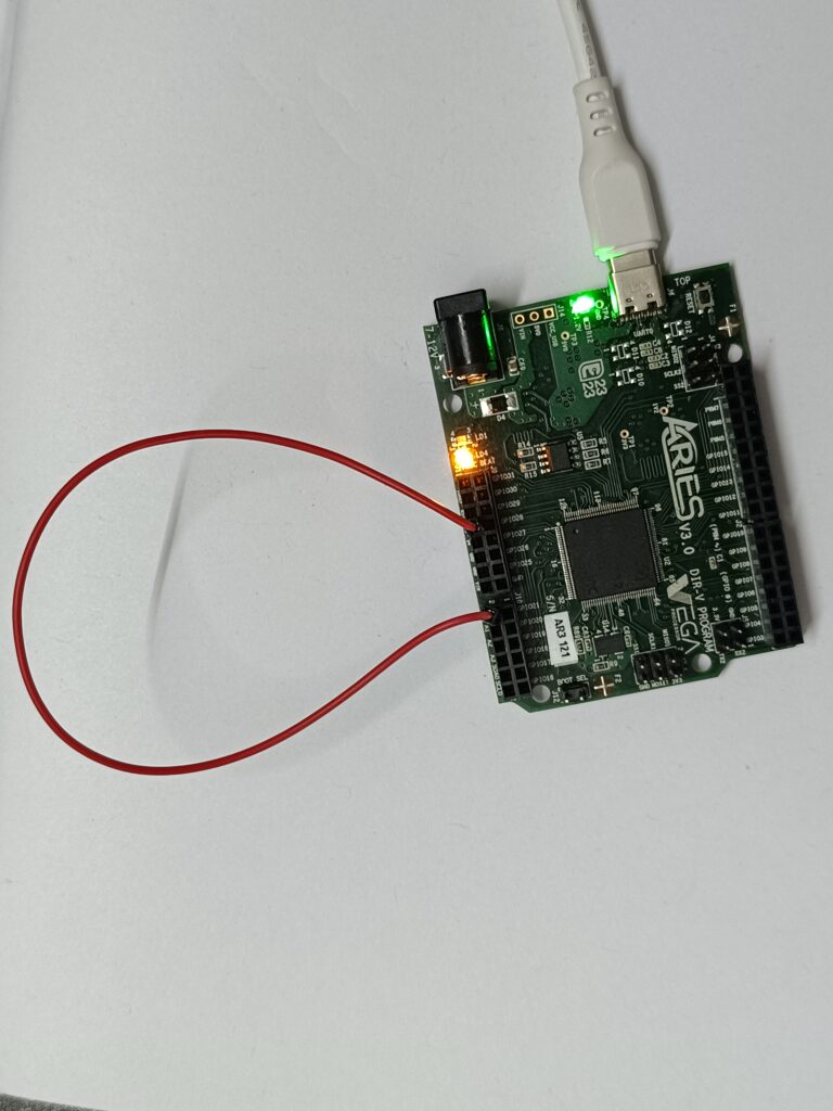
M-M wire connected to VCC (3.3V)
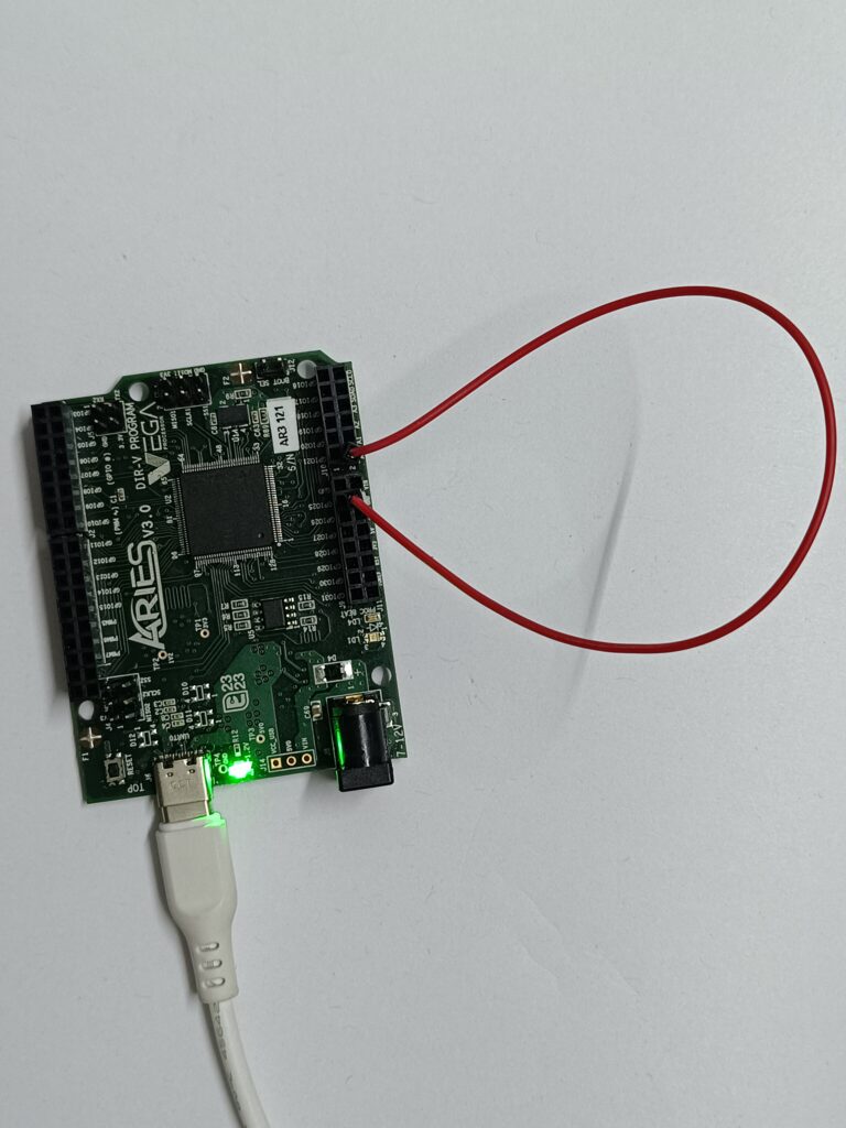
M-M wire connected to GND
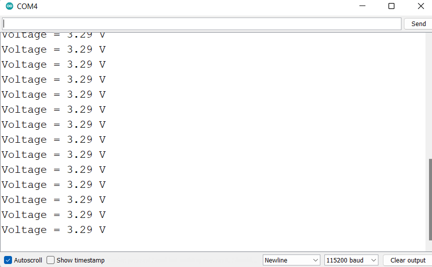
Output when connected to VCC (3.3V)
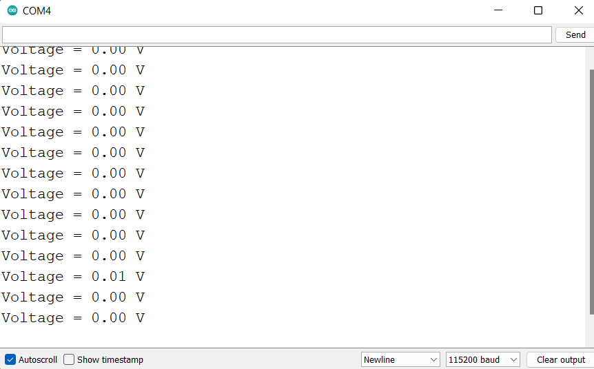
Output when connected to GND (0 V)