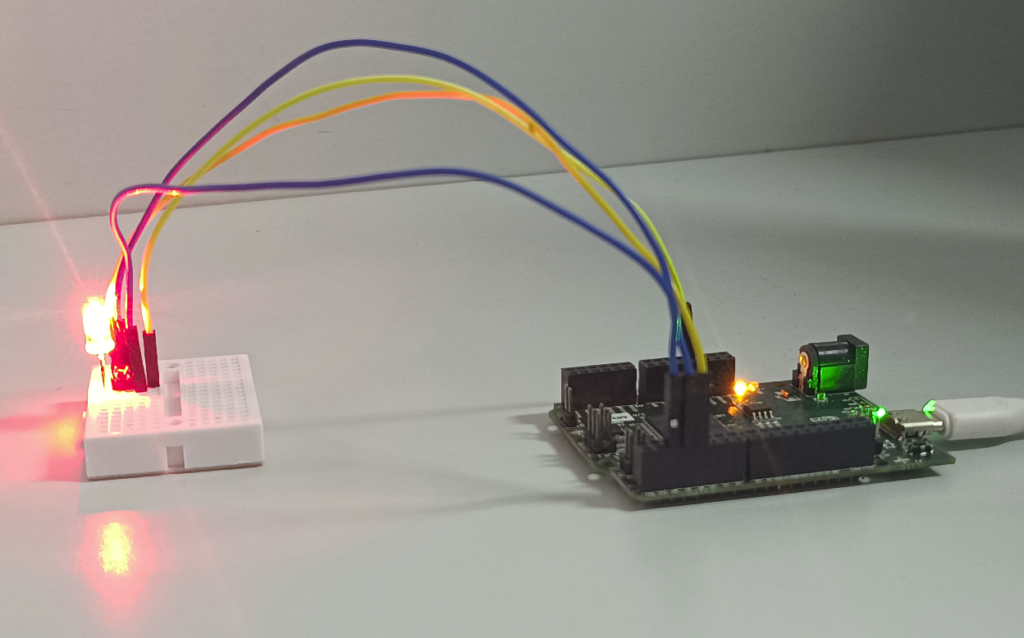
In this tutorial we will see how to connect the RGB LED with ARIES v3.0 Board. The RGB LED can emit different colors by mixing the 3 basic colors red, green and blue.
RGB LED
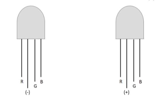
RGB LED also known as Tricolour LED have three LEDs inside them and usually, these three internal LEDs share either a common anode (Common positive) or a common cathode (Common Negative) in a through-hole package. In Common Cathode type LEDs, there will be three positive terminals each terminal representing a colour and one negative terminal representing all three colours. In Common Anode, there will be three negative terminals each terminal representing a colour and one positive terminal representing all three colours.
For Common Cathode type, If we want RED to be ON, we need to power the RED LED pin and ground the common negative. The same goes for all the LEDs. In Common Anode type, if we want RED to be on in above, we need to ground the RED LED pin and power the common positive. The same goes for all the LEDs. To produce other colours, you can combine the three colours in different intensities.
Prerequisites
- Windows 10 or above/Linux (64 bit)
- Arduino IDE
- VEGA ARIES Board support package
Components Required
- RGB LED
- ARIES v3.0 Board
- Jumper Wires
- USB type C to USB type A cable
- Resistor (40 Ohm)
Circuit Diagram:

You cannot distinguish between the common cathode and common anode type by just looking at the RGB led because both look same. You will have to make the connections to see that either it is common cathode or common anode. The RGB led has one big lead than the other leads. In the common cathode case, it will be connected to GND and in the common anode case; it will be connected to 3.3V. The other leads can be connected to any GPIO pins.
Connections:
| RGB LED | ARIES v3.0 Board |
| Longest lead | GND/3.3V |
| R | GPIO-0 |
| B | GPIO-1 |
| G | GPIO-2 |
Once we are done with the connections, let’s power up the ARIES v3 board via the USB port of a Laptop/Desktop/PC and burning the code into the ARIES v3 board, we have to use a USB type C to USB type A cable. The cable should be connected to UART-0 port of the ARIES v3 board, and the Laptop/Desktop/PC should be preinstalled with Arduino IDE and VEGA ARIES boards of latest version.
Procedure
Open and set up the Arduino IDE as described in Getting Started with ARIES v3.0.
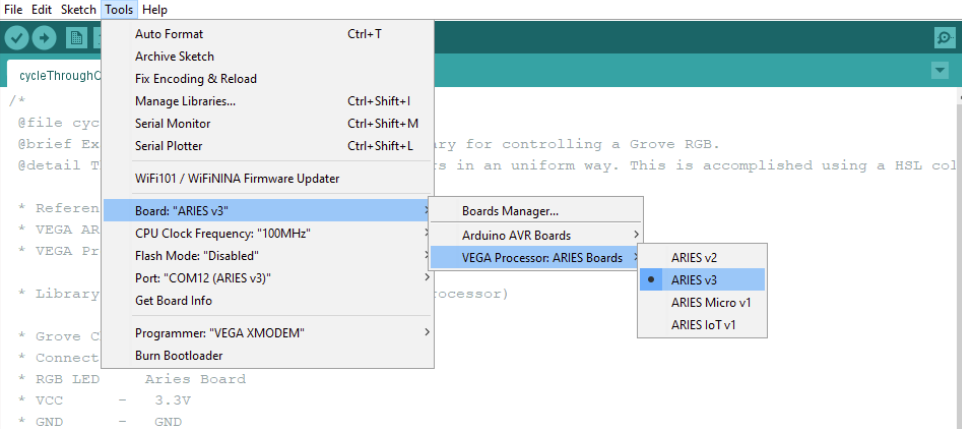
- Make sure you have selected ARIES v3 Board from Tools -> Board -> VEGA Processor: ARIES Boards -> ARIES v3
- Select Programmer as VEGA XMODEM from Tools -> Programmer -> VEGA XMODEM
- Also select appropriate port from Tools -> Port -> COM* (ARIES v3)
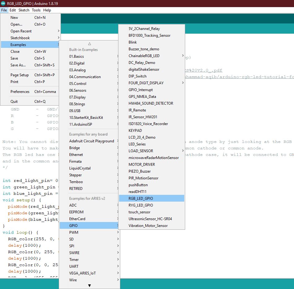
Now, Open Files -> Examples -> Under Examples for ARIES v3 -> GPIO -> RGB_LED_GPIO
Finally, let’s Upload the code to ARIES v3 Board.
Output
Once the code is uploaded, you can see the RGB LED working as expected by producing different colours.