In this tutorial, we are going to learn how to interface MPU6050 with ARIES v3 Board. The MPU6050 sensor module is a complete 6-axis Motion Tracking Device. It combines 3-axis Gyroscope, 3-axis Accelerometer, and Digital Motion Processor all in a small package. Also, it has the additional feature of an on-chip temperature sensor.
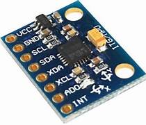
MPU6050(Gyroscope + Accelerometer + Temperature)
As we said, The MPU6050 is a Micro-Electro-Mechanical System (MEMS) which consists of a 3-axis Accelerometer and 3-axis Gyroscope inside it. This helps us measure acceleration, velocity, orientation, displacement, and many other motion-related parameters of a system or object. This module also has a (DMP) Digital Motion Processor inside it which is powerful enough to perform complex calculations and thus free up the work for Microcontroller.
The MPU6050 module allows us to read data from it through the I2C bus. Any change in motion will be reflected on the mechanical system which will, in turn, vary the voltage. Then the IC has a 16-bit ADC which it uses to accurately read these changes in voltage and stores it in the FIFO buffer.
DMP (Digital Motion Processor)
The embedded Digital Motion Processor (DMP) is used to compute motion processing algorithms. It takes data from gyroscope, accelerometer, and additional 3rd party sensor such as magnetometer and processes the data. It provides motion data like roll, pitch, yaw angles, landscape and portrait sense, etc. It minimizes the processes of the host in computing motion data. The resulting data can be read from DMP registers.
Prerequisites
- Windows 10 or above/Linux (64 bit)
- Arduino IDE
- VEGA ARIES Board support package
Components Required
- ARIES v3.0 Board
- USB type C to USB type A cable
- MPU6050
- Jumper Wires
Note: All of the following boards can be used for this project
Connection Diagram
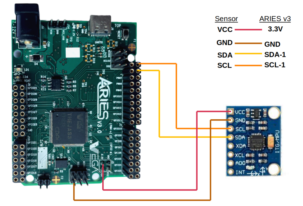
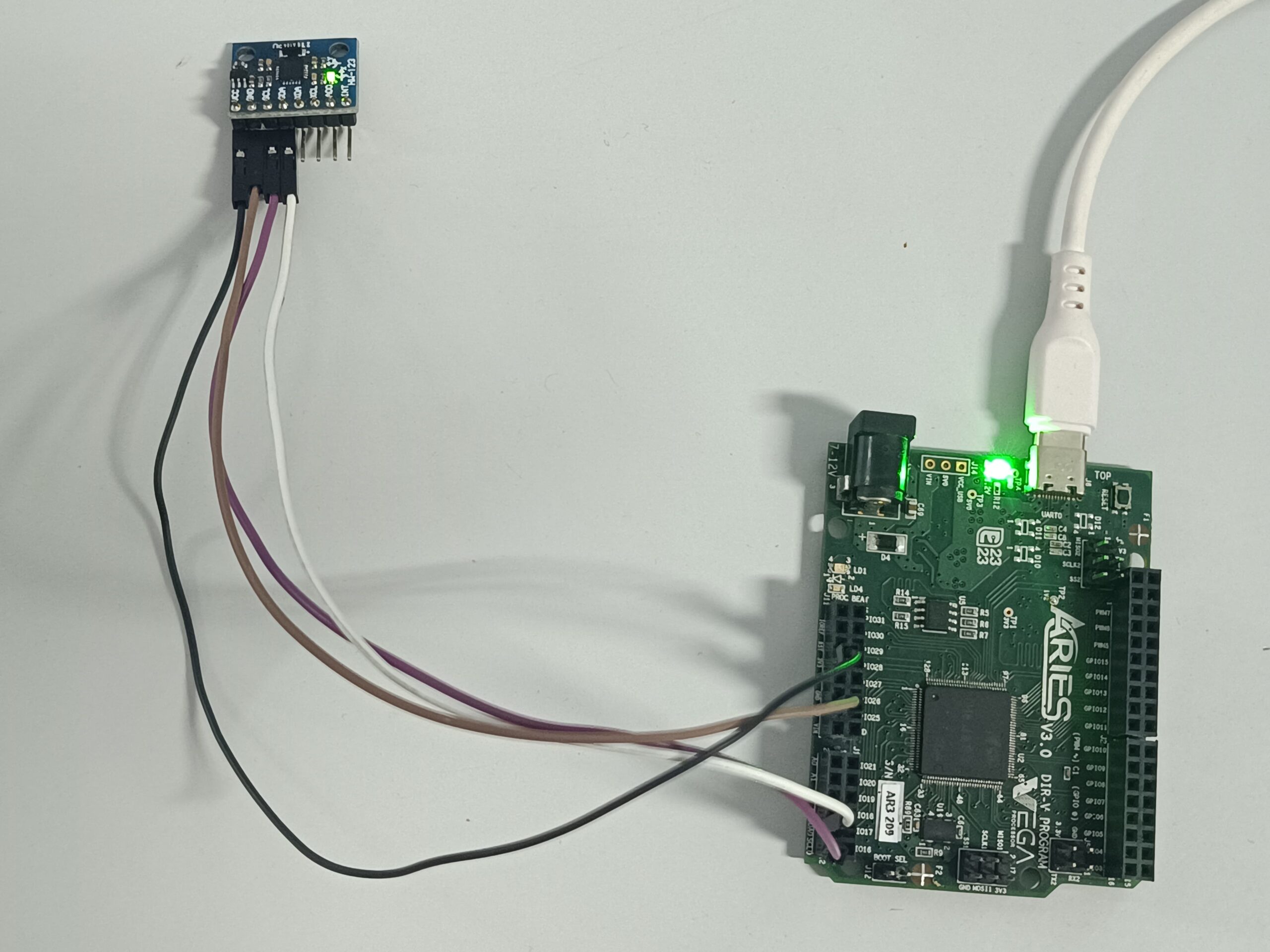
MPU6050 communicates with the ARIES v3 board via the I2C-1 port. MPU6050 is composed of 8 pins, but we need only 5 pins for the working, VCC, GND, and two I2C pins(SCL and SDA). Connect VCC and GND to +3.3V and GND respectively of ARIES v3 board. Connect SCL of the sensor to SCL_1 and SDA of the sensor to SDA_1 of ARIES v3 board.
Now, for powering up and programming the code into the ARIES v3 board, we have to connect a USB type C (common data cable, used for mobile charging and data transfer) in the UART0 port of the ARIES v3 board, to a Laptop/Desktop/PC .
| MPU6050 | ARIES v3 Board |
| VCC | +3V3 |
| GND | GND |
| SCL | SCL-1 |
| SDA | SDA-1 |
Procedure
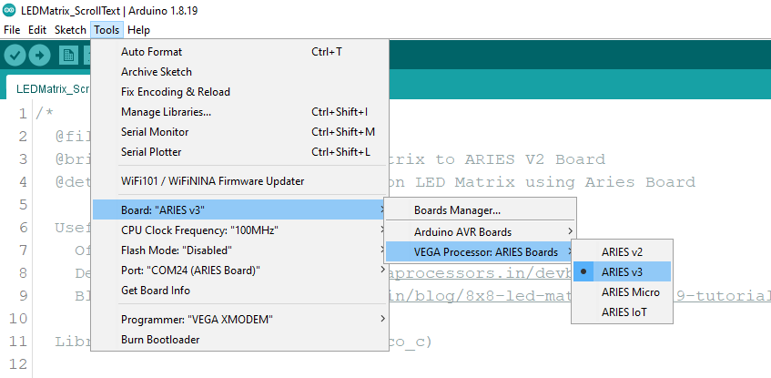
Open and set up the Arduino IDE as described in Getting Started with ARIES v3.0.
- Make sure you have selected ARIES v3 Board from Tools -> Board -> VEGA Processor: ARIES Boards -> ARIES v3
- Select Programmer as VEGA XMODEM from Tools -> Programmer -> VEGA XMODEM
- Also select appropriate port from Tools -> Port -> COM* (ARIES Board)
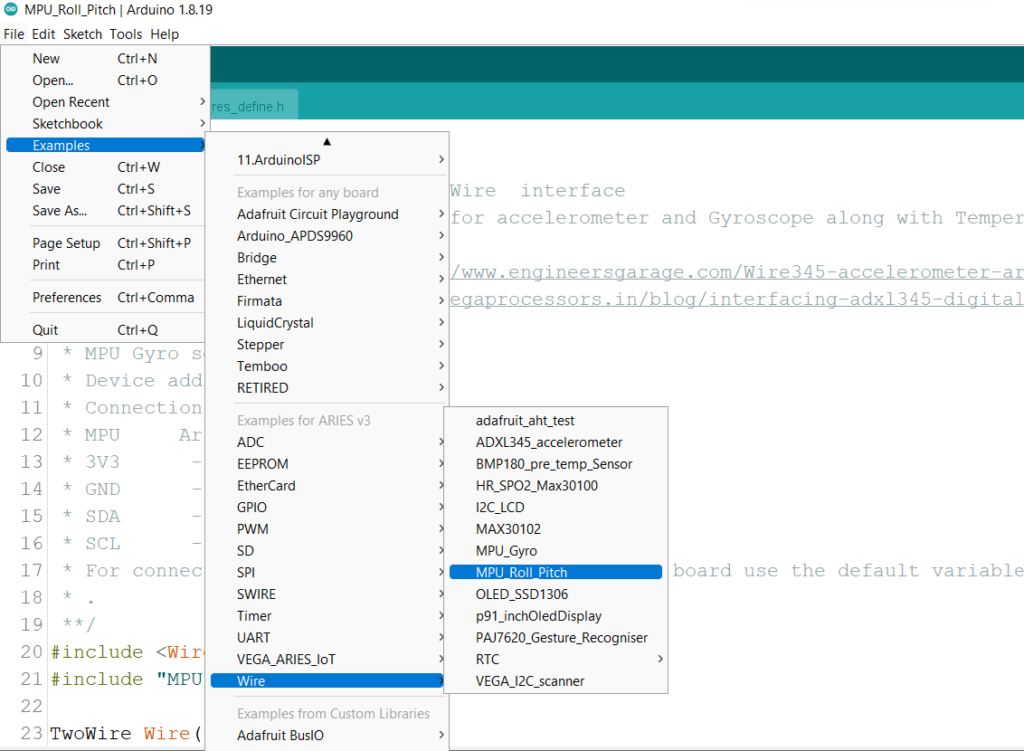
Now, Open Files -> Examples -> Under Examples for ARIES v3 -> Wire-> MPU_Roll_Pitch
Finally upload the code.
Output
Once the program is uploaded, Open the serial monitor, you can see the X,Y,Z values for accelerometer and Gyroscope along with Temperature, Roll and pitch values using MPU6050 in the serial monitor of Arduino IDE
