In this tutorial, we are going to learn how to interface MPU6050 with ARIES v2 Board. The MPU6050 sensor module is a complete 6-axis Motion Tracking Device. It combines 3-axis Gyroscope, 3-axis Accelerometer, and Digital Motion Processor all in a small package. Also, it has the additional feature of an on-chip temperature sensor.
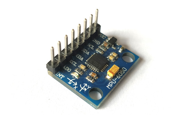
MPU6050(Gyroscope + Accelerometer + Temperature)
As we said, The MPU6050 is a Micro-Electro-Mechanical System (MEMS) which consists of a 3-axis Accelerometer and 3-axis Gyroscope inside it. This helps us measure acceleration, velocity, orientation, displacement, and many other motion-related parameters of a system or object. This module also has a (DMP) Digital Motion Processor inside it which is powerful enough to perform complex calculations and thus free up the work for Microcontroller.
The MPU6050 module allows us to read data from it through the I2C bus. Any change in motion will be reflected on the mechanical system which will, in turn, vary the voltage. Then the IC has a 16-bit ADC which it uses to accurately read these changes in voltage and stores it in the FIFO buffer.
DMP (Digital Motion Processor)
The embedded Digital Motion Processor (DMP) is used to compute motion processing algorithms. It takes data from gyroscope, accelerometer, and additional 3rd party sensor such as magnetometer and processes the data. It provides motion data like roll, pitch, yaw angles, landscape and portrait sense, etc. It minimizes the processes of the host in computing motion data. The resulting data can be read from DMP registers.
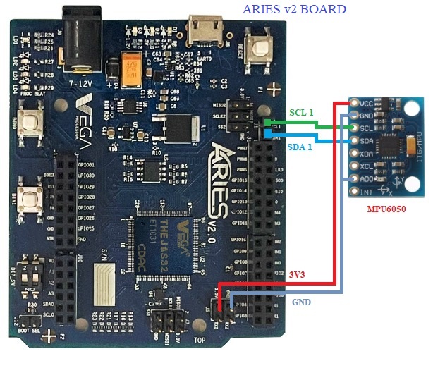
Circuit Diagram
MPU6050 communicates with the ARIES v2 board via the I2C1 port. MPU6050 is composed of 8 pins, but we need only 5 pins for the working, VCC, GND, two I2C pins(SCL and SDA), and AD0 pin. Connect VCC and GND to +3.3V and GND respectively of ARIES v2 board. Connect SCL of the sensor to SCL_1 and SDA of the sensor to SDA_1 of ARIES v2 board. Then connect AD0 pin with GND pin for selecting default address.
Now, for powering up and programming the code into the ARIES v2 board, we have to connect a micro USB type B (common data cable, used for mobile charging and data transfer) in the UART0 port of the ARIES v2 board, to a Laptop/Desktop/PC with preinstalled VEGA SDK and Toolchain.
| MPU6050 | ARIES v2 Board |
| VCC | +3V3 |
| GND | GND |
| SCL | SCL-1 |
| SDA | SDA-1 |
| AD0 | GND |
Procedure
After setting up the toolchain and SDK path environments, build the example program for the MPU6050 sensor by:
cd vega-sdk/vega-sdk/examples/i2c/mpu6050_sensor_demomake clean command to clean the executable :
make cleanthen use the make command to build it.
makeNow, we can transfer the built program to the board, before transfer please ensure that you have connected the UART0 connector of the board to the PC.
Open a new terminal and execute the following command.
sudo minicom ariesNow you can see the minicom terminal opened and the board UART terminal is ready.
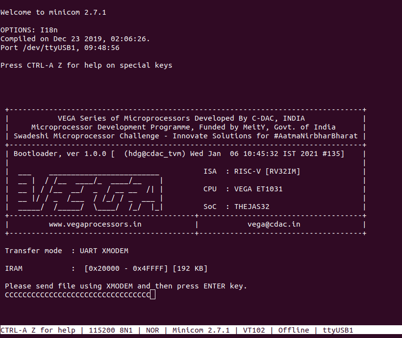
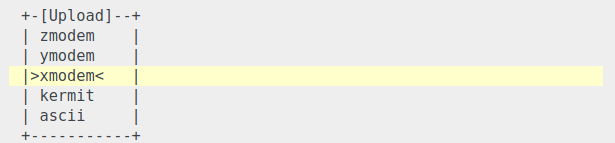
Use CTRL+A S to enter the file sending menu and select xmodem by pressing Enter.
In the next window, with the space bar select the mpu6050_sensor_demo.bin file to be transferred, by pressing Enter, the transfer process starts.
Wait until the process is completed. The screen should display how much data has been transferred.
After completing the transfer the Program will start to execute
The output is displayed in the minicom UART terminal:
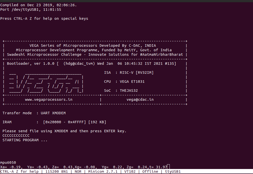
Xa, Ya, Za —> 3-axis accelerometer output
Xg,Yg,Zg —> 3-axis gyroscope output
t –> temperature
For additional pieces of information:
https://invensense.tdk.com/wp-content/uploads/2015/02/MPU-6000-Datasheet1.pdf