In this tutorial, we will see how we can interface a microphone sound detector sensor with ARIES V3 board. A microphone sound detector sensor is a device that can be used to detect presence of sound.
Sound Detector
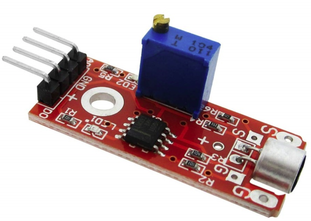
The sound sensor is a small board that incorporates a microphone and some processing circuitry to convert the sound wave into an electrical signal. It gives a measurement of how loud a sound is. These sound sensors are capable of detecting voice, claps, or door knocks. You can use them for a variety of sound-reactive projects, such as making your lights clap-activated or monitoring your pets while you’re away.
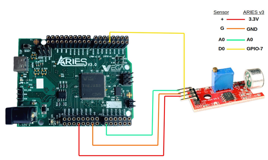
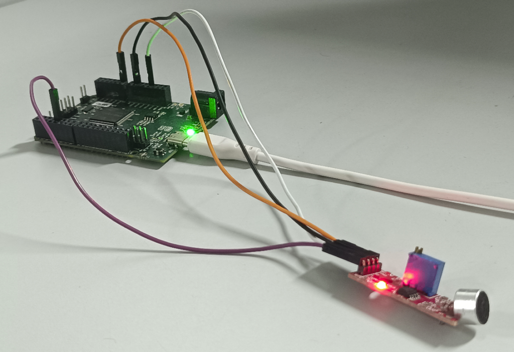
The linear HW-484 V0.2 sound detector sensor has four pins: A0, G,+ and D0. Connect + and G of sound sensor module to 3.3V and GND respectively of ARIES v3 board. Then connect the A0 Pin of the sound sensor to the A0 pin of ARIES v3 and D0 pin of sensor to GPIO-7 of ARIES board for getting the output.
| Sound Detector Sensor | ARIES V3 board |
| G | GND |
| + | 3.3 V |
| A0 | A0 |
| D0 | GPIO-7 |
Components Required
- ARIES v3 Microcontroller
- HW-484 V0.2 Microphone sound detector Sensor
- Jumper wires
Connection Diagram
Now, for powering up the ARIES v3 board via the USB port of a Laptop/Desktop/PC and burning the code into the ARIES v3 board, we have to use a micro USB type C to USB type A cable. The cable should be connected to UART-0 port of the ARIES v3 board, and the Laptop/Desktop/PC should be preinstalled with Arduino IDE and VEGA ARIES boards of latest version.
Procedure
Here we are using Arduino IDE 1.8.19 in Ubuntu OS for testing the code.
Open Arduino IDE
Go to Tools -> Board -> VEGA Processor ARIES Boards -> Select ARIES v3
Go to Tools -> Programmer -> Select VEGA XMODEM
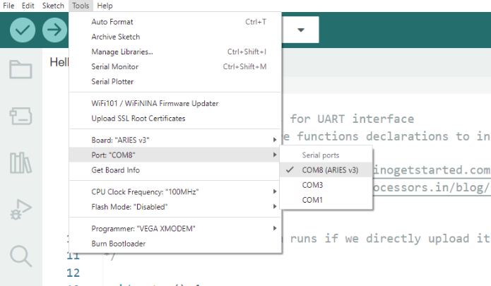
Connect the ARIES v3 board to PC
Go to Tools -> Port -> Select the appropriate port
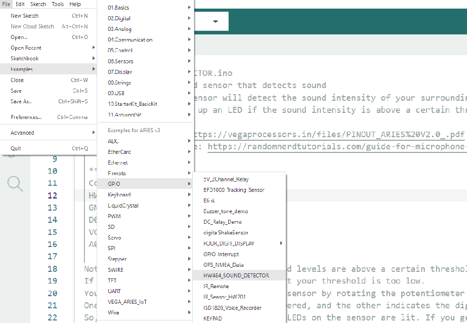
Open File -> Examples -> Examples for ARIES v3 ->GPIO -> Open HW484_SOUND_DETECTOR example
Output
Once you’ve completed the code, upload it to your ARIES v3.0 board using the Arduino IDE. Wait until the program is uploaded. After completing the uploading the program will start to execute. Once the code is uploaded show a magnet in front of the sensor and observe the changes happening to the values in serial monitor.
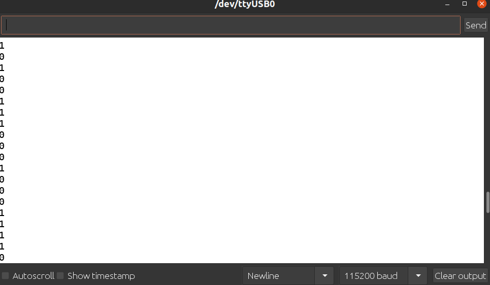
That example outputs 1, if the sound levels are above a certain threshold, and 0, if they are below.
If you are always getting 1, it means that your threshold is too low. You need to adjust the threshold of your sensor by rotating the potentiometer at the back. One LED indicates the sensor is being powered, and the other indicates the digital output. So, if you are always getting 1, the two LEDs on the sensor are lit. If you get 0, the second LED should be off.
Here in the example code you will get a 1 in serial monitor if sound beyond the Threshold value is detected and the onboard Green LED will be ON. If sound is below the threshold value, then onboard Green LED will be OFF and values coming in the serial monitor will be 0.
Demonstration
Here we have used a piezo buzzer as a sound source, whenever the buzzer produces sound the sound detector sensor will detect the sound and onboard GREEN LED in ARIES board will turn ON otherwise it will be off by default.