In this tutorial, we will learn about the CAN Bus protocol by Interfacing MCP2515 CAN Bus Module with VEGA ARIES Boards.
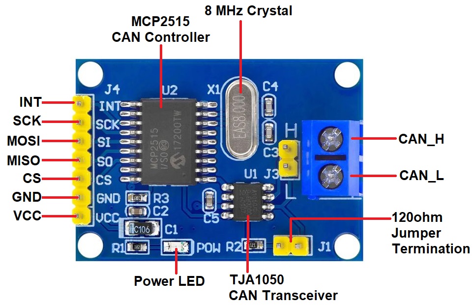
MCP2515 CAN Bus Controller Module
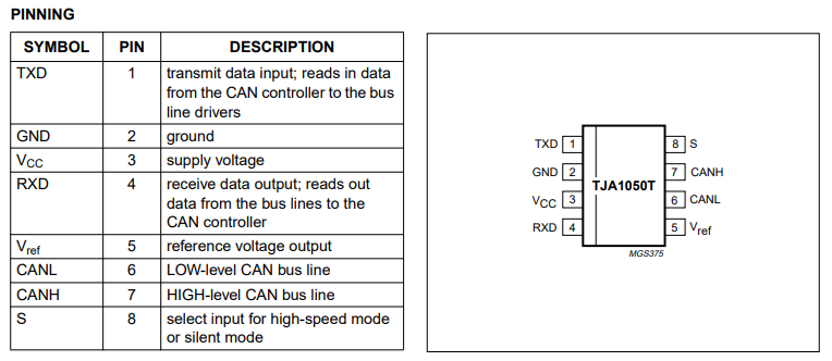
Microchip Technology’s MCP2515 is a stand-alone Controller Area Network (CAN) controller that implements the CAN specification, Version 2.0B. It is capable of transmitting and receiving both standard and extended data and remote frames. The MCP2515 has two acceptance masks and six acceptance filters that are used to filter out unwanted messages, thereby reducing the host MCU’s overhead. The MCP2515 interfaces with microcontrollers (MCUs) via an industry standard Serial Peripheral Interface (SPI).
For more information refer to MCP2515 Datasheet which has a detailed guide.
Prerequisites
- Windows 10 or above/Linux (64 bit)
- Arduino IDE
- VEGA ARIES Board support package
Components Required
- ARIES v3.0 Board
- ARIES v2.0 Board
- MCP2515 CAN Bus Controller Module * 2
- USB type C to USB type A cable
- Micro USB type B to USB type A cable
- Jumper Wires
Libraries Required
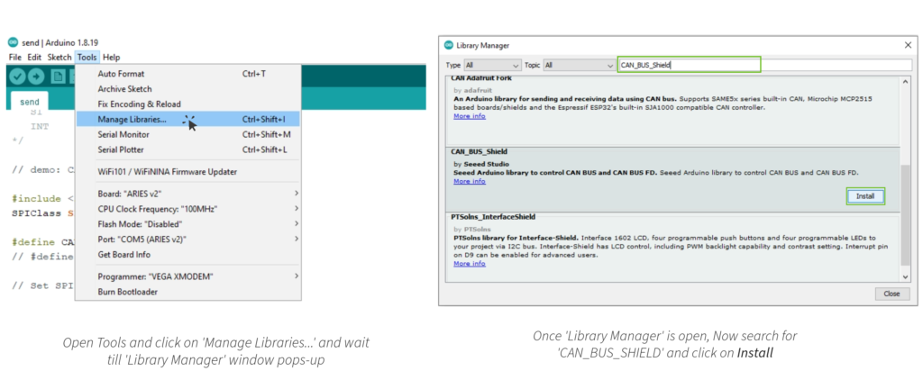
Download the CAN_BUS_SHIELD Library by Seeed Studio from Tools -> Manage Libraries…
Circuit Diagram
Now let us interface MCP2515 CAN Bus Module with ARIES and test the CAN Communication protocol. We will transmit the character array of size 8 over a CAN Bus with the help of pair of ARIES Boards & MCP2515 CAN Module. Here is the simple connection diagram.
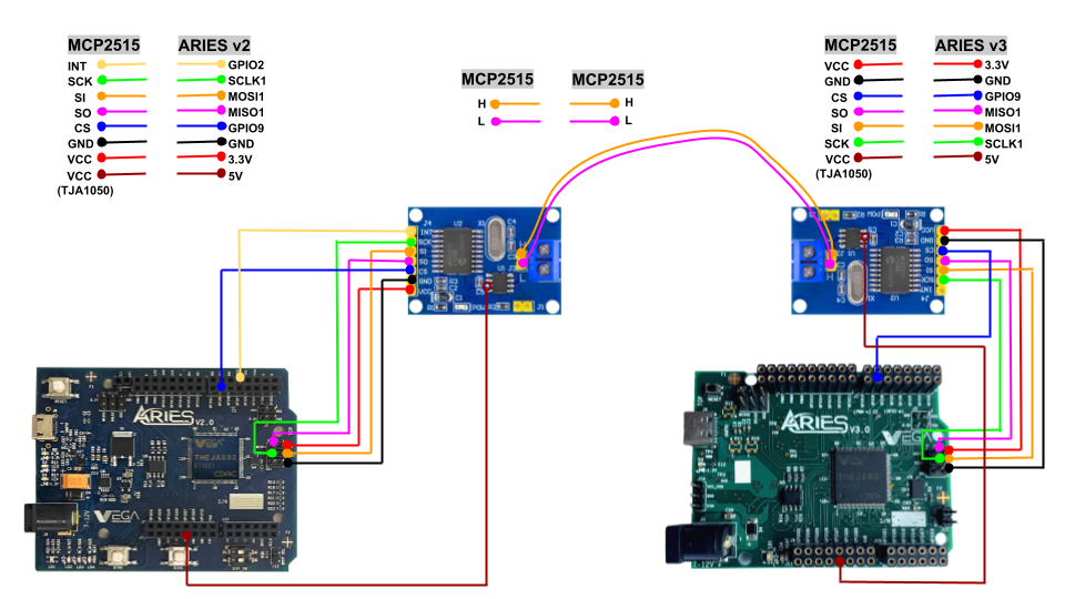
The left part consisting of ARIES v2.0 Board connected to CAN Module using SPI protocol, which is a receiver part. Similarly, the right part consisting of ARIES v3.0 Board & CAN Module which is the transmitter part.
The transmitter & Receiver Part is connected to each other with the help of the MCP2515 CAN Bus Module. The CAN_H & CAN_L of the transmitter are connected to the CAN_H & CAN_L of the receiver respectively.
Connections
The connection between ARIES Board & MCP2515 CAN Module is as follows.
| MCP2515 CAN Bus Module | ARIES V2.0 Board |
| VCC | 3.3V |
| GND | GND |
| CS | GPIO-9 |
| SO | MISO-1 |
| SI | MOSI-1 |
| SCK | SCLK-1 |
| INT | GPIO-2 |
| VCC (TJA1050) | 5V |
| MCP2515 CAN Bus Module | ARIES V3.0 Board |
| VCC | 3.3V |
| GND | GND |
| CS | GPIO-9 |
| SO | MISO-1 |
| SI | MOSI-1 |
| SCK | SCLK-1 |
| INT | – |
| VCC (TJA1050) | 5V |
| MCP2515 CAN Bus Module (Receiver) | MCP2515 CAN Bus Module (Transmitter) |
| H | H |
| L | L |
Procedure
Once we’re done with the connections, let’s power up both the board. Make sure the Laptop/Desktop/PC which we’re using should be preinstalled with Arduino IDE and VEGA ARIES boards of latest version.
- Now, Open the Arduino IDE
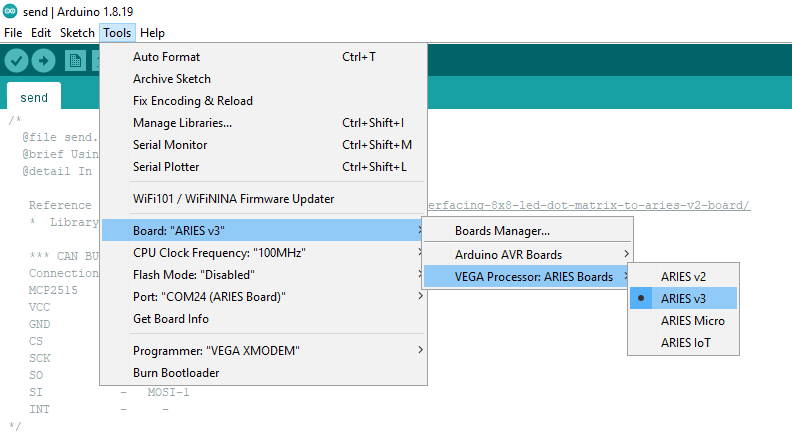
- The code is divided into two parts one as CAN transmitter code (ARIES v3) and the other as CAN Receiver code (ARIES v2). First, we will upload the transmitter code, so make sure you have selected ARIES v3 Board from Tools -> Board -> VEGA Processor: ARIES Boards -> ARIES v3
- Select Programmer as VEGA XMODEM from Tools -> Programmer -> VEGA XMODEM
- Also select appropriate port, Tools -> Port -> COM* (ARIES Board)
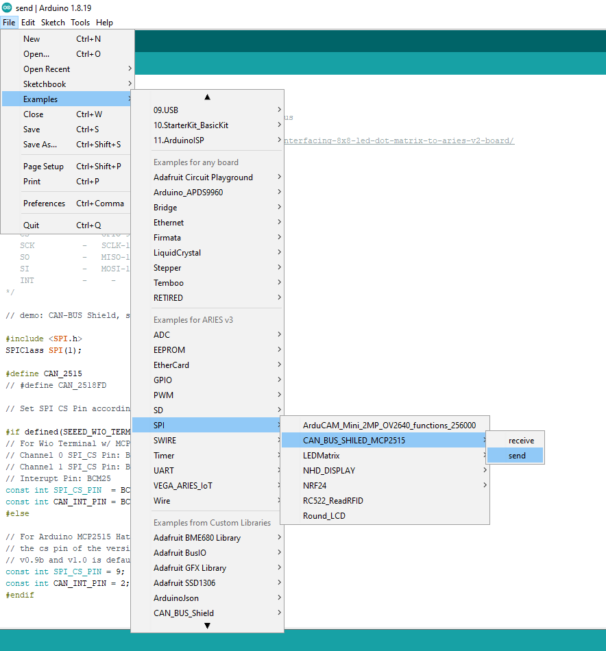
- Open File -> Examples -> Under Examples for ARIES v3 -> SPI -> CAN_BUS_SHIELD_MCP2515 -> send
- Now let’s Upload the send/transmitter code.
- Once the transmitter/send code is uploaded successfully, Now let’s upload the Receiver code. For that select ARIES v2 Board from Tools -> Board -> VEGA Processor: ARIES Boards -> ARIES v2
- Also select appropriate port, Tools -> Port -> COM* (ARIES Board)

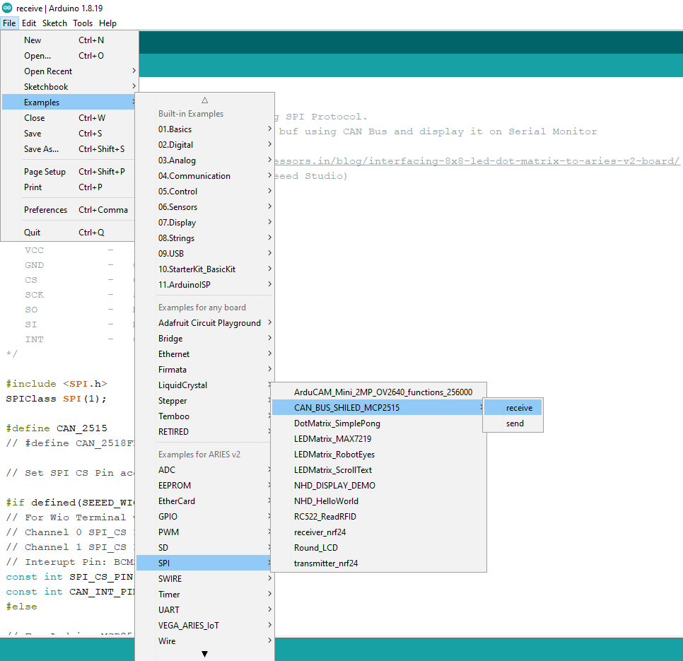
- Now, open File -> Examples -> Under Examples for ARIES v2 -> SPI -> CAN_BUS_SHIELD_MCP2515 -> receive
- Finally Upload the receiver code.
Output
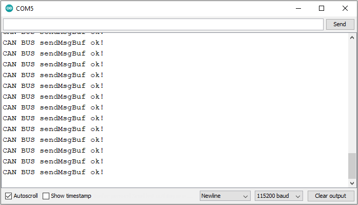
After uploading sender/transmitter code in ARIES v3, character array of size 8 with initially value of all elements equals to 0 will start transmitting through CAN_H & CAN_L pins. The last element (index-7th) will start incrementing by 1. When the index-7th element value get equals to 100, it will reset to 0 and second last element (index-6th) will increment by 1. For every value of index-7th equals to 100, index-6th element will increment by 1. Similarly for every index-6th element value equal to 100, index 5th element will increment by 1. And these all updated values will continuously transmit to receivers end (ARIES v2) after every 100 ms delay. On successful transmission below message will display on Serial monitor.
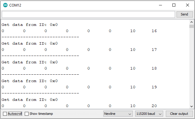
When the receiver code is uploaded in ARIES v2 (receiver), it will continuously check if the data is receiving through CAN_L & CAN_H pins. If it receives the data, it will get its length and read the data into the buffer. Also, it will read its CAN ID and prints the data, and the CAN ID continuously on serial monitor as shown below.