This tutorial is about interfacing the LDR sensor module with ARIES v3 Board. The LDR is definitely the most popular and cheap light sensor in robotics. The sensor is also known as a photo resistor due to its resistance that varies with the amount of light falling on it.
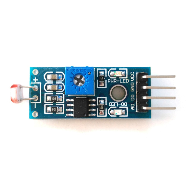
LM393 Optical Photosensitive LDR Sensor Module
LDR sensor module is used to detect the intensity of light. It has both analog output pin and digital output pin labeled AO and DO, respectively. When there is light, the resistance of LDR will become low according to the intensity of light. The greater the intensity of light, the lower the resistance of LDR. The sensor module has a potentiometer knob that can be adjusted to change the sensitivity of LDR towards the light. These LDRs or Photo resistors work on the principle of Photo Conductivity.
Prerequisites
- Windows 10 or above/Linux (64 bit)
- Arduino IDE
- VEGA ARIES Board support package
Components Required
- ARIES v3.0 Board
- USB type C to USB type A cable
- LDR sensor
- Jumper Wires
Circuit Diagram
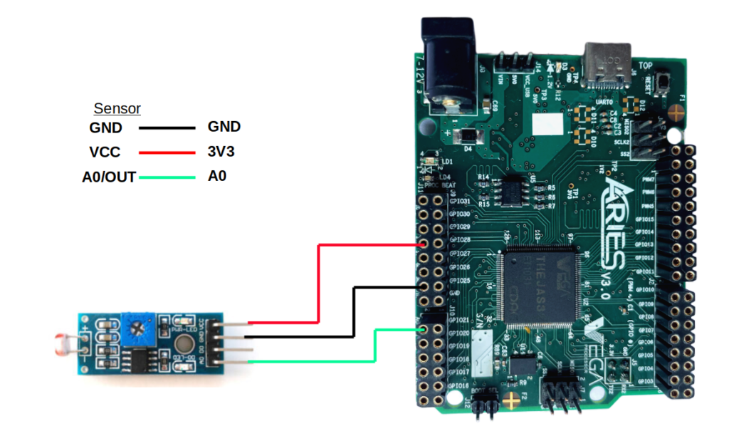
Connections:
| LDR sensor | ARIES V3 board |
| GND | GND |
| VCC | 3V3 |
| A0/AOUT | A0 |
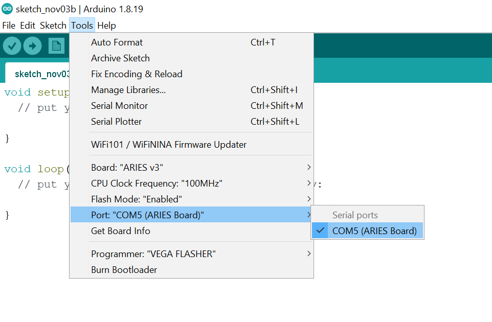
Procedure
Open and set up the Arduino IDE as described in Getting Started with ARIES v3.0.
- Make sure you have selected ARIES v3 Board from Tools -> Board -> VEGA Processor: ARIES Boards -> ARIES v3
- Select Tools -> Flash Mode -> Enabled
- Select Programmer as VEGA FLASHER from Tools -> Programmer -> VEGA FLASHER
- Also select appropriate port from Tools -> Port -> COM* (ARIES Board)
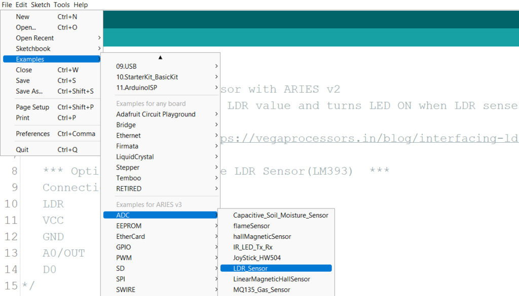
Now, Open Files -> Examples -> Under Examples for ARIES v3 -> ADC->LDR_Sensor
Finally Upload the code to ARIES v3.0 board
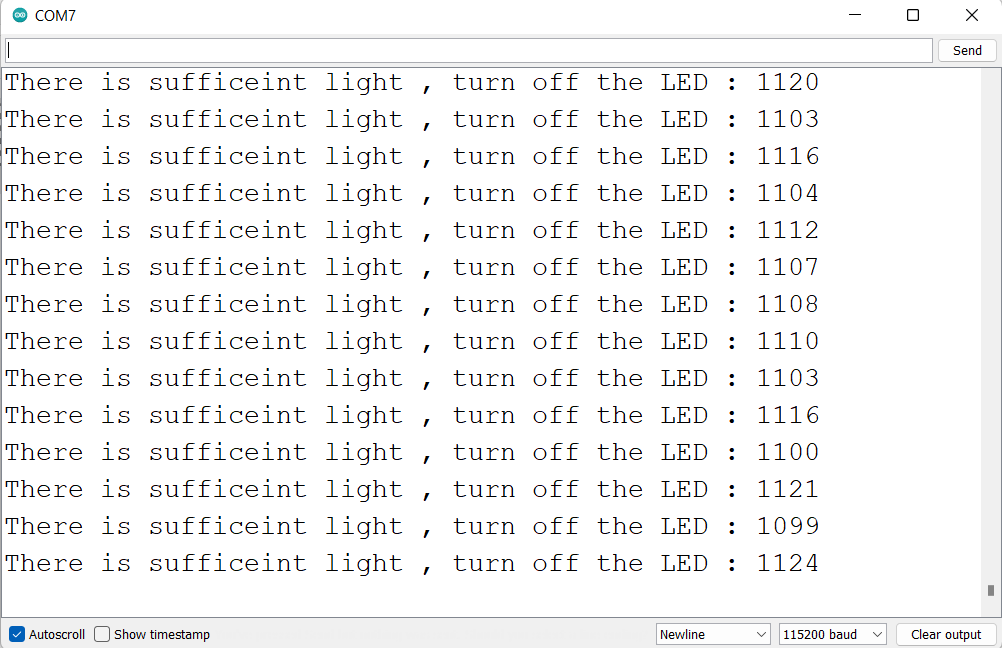
Output
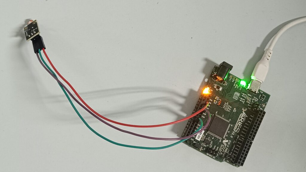
This demo reads the LDR value and turns LED ON when LDR senses darkness. The analog readings corresponding to the light and darkness will be displayed in serial monitor.