This tutorial is about interfacing the LDR sensor module with ARIES v2 Board. The LDR is definitely the most popular and cheap light sensor in robotics. The sensor is also known as a photo resistor due to its resistance that varies with the amount of light falling on it.
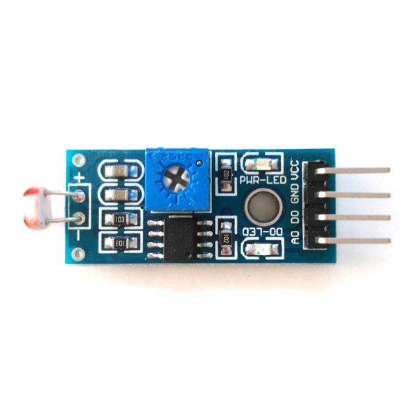
LM393 Optical Photosensitive LDR Sensor Module
LDR sensor module is used to detect the intensity of light. It has both analog output pin and digital output pin labeled AO and DO, respectively. When there is light, the resistance of LDR will become low according to the intensity of light. The greater the intensity of light, the lower the resistance of LDR. The sensor module has a potentiometer knob that can be adjusted to change the sensitivity of LDR towards the light. These LDRs or Photo resistors work on the principle of Photo Conductivity.
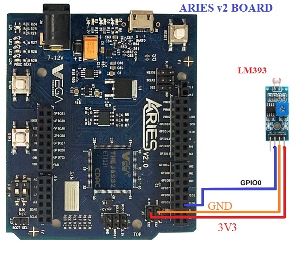
Circuit Diagram
The LDR sensor module has 4 pins. Connect VCC and GND of the sensor module to +3.3V and GND respectively of ARIES v2 board. Then connect D0 pin of sensor module to GPIO0 pin of ARIES v2 Board.
Now, for powering up the ARIES v2 board via USB port of a Laptop/Desktop/PC and burning the code into the ARIES v2 board, we have to use a micro USB type B to USB type A cable. The cable should be connected to UART0 port of the ARIES v2 board, and the Laptop/Desktop/PC should be preinstalled with VEGA SDK and Toolchain.
| Proximity Sensor | ARIES v2 Board |
| VCC | 3.3V |
| GND | GND |
| D0 | GPIO0 |
Procedure
After setting up the toolchain and SDK path environments, build the example program for the LDR Sensor module by:
cd vega-sdk/examples/gpio/ldr_sensor_pgmclean command to clean the executable :
make cleanthen use make command to build it.
makeNow, we can transfer the built program to the board, before transfer please ensure that you have connected UART0 to the PC.
Open a new terminal and execute the following command.
sudo minicom ariesNow you can see the minicom terminal opened and the board UART terminal is ready.
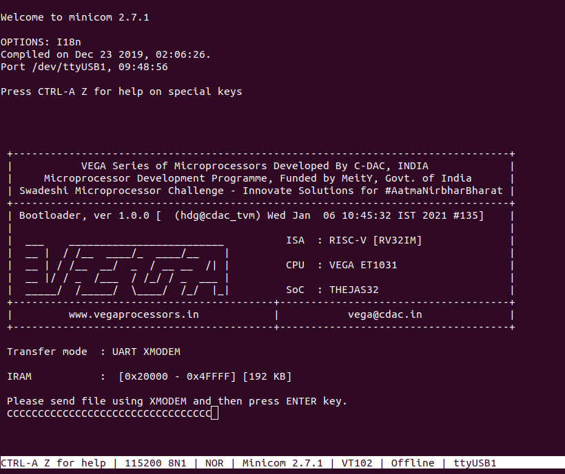
Use CTRL+A S to enter file sending menu and select xmodem by pressing Enter.
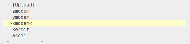
In the next window, with the space bar select the ldr_sensor_pgm.bin file to be transferred, by pressing Enter, the transfer process starts.
Wait until the process is completed. The screen should display how much data has been transferred.
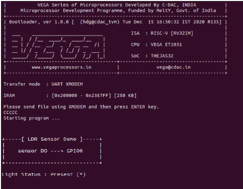
After completing transfer the Program will start to execute.
When the LDR is exposed to light the following status is displayed on minicom UART terminal:
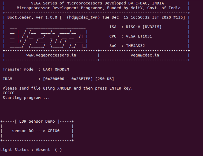
When the LDR is not exposed to light the following status is displayed on minicom terminal:
for additional information:
https://content.instructables.com/ORIG/FSN/DK3E/JT4TLIOY/FSNDK3EJT4TLIOY.pdf