In this tutorial, we will see how we can interface GSM SIM800A module with ARIES v3.0 Board for calling purpose.
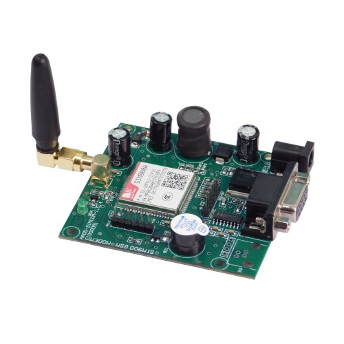
GSM – SIM 800A
SIM800A is a Dual-band GSM/GPRS module that works on frequencies EGSM 900MHz and DCS 1800MHz. SIM800A features GPRS multi-slot class 12/ class 10 (optional) and supports the GPRS coding schemes CS-1, CS-2, CS-3 and CS-4. With a tiny configuration of 24*24*3mm, SIM800A can meet almost all the space requirements in user’s applications, such as smart phone, PDA and other mobile devices.
Features:
- Support Bluetooth function.
- Programmable general purpose input and output.
- Power supply voltage of board: 12V
- Dual-Band 900/1800MHz
- GPRS multi-slot class 12/10/8
- GPRS mobile station class B
Prerequisites
- Windows 10 or above/Linux (64 bit)
- Arduino IDE
- VEGA ARIES Board support package
Components Required
- ARIES v3.0 Board
- USB type C to USB type A cable
- GSM SIM800A MODULE
- Jumper Wires
- Power Supply (7-12V)
Circuit Diagram:
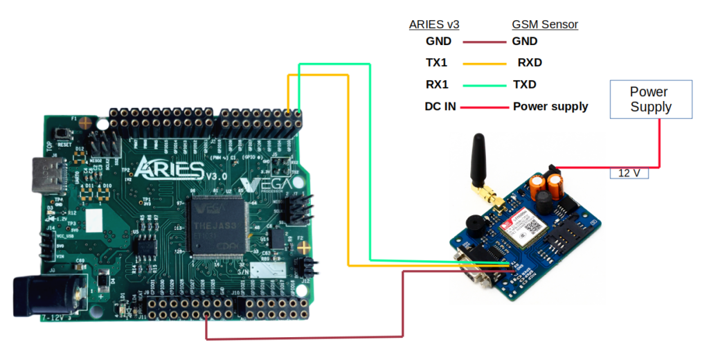
Connections:
| GSM SIM800A | ARIES V3 board |
| GND | GND |
| VCC | 12V (connect DC IN of SIM800A module using 12V adapter) |
| RXD | TX-1 |
| TXD | RX-1 |
Procedure
Open and set up the Arduino IDE as described in Getting Started with ARIES v3.0.
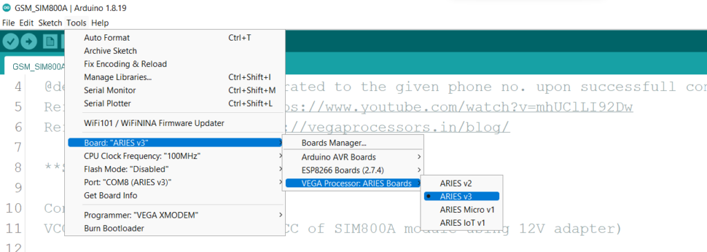
- Make sure you have selected ARIES v3 Board from Tools -> Board -> VEGA Processor: ARIES Boards -> ARIES v3
- Select Programmer as VEGA XMODEM from Tools -> Programmer -> VEGA XMODEM
- Also select appropriate port from Tools -> Port -> COM* (ARIES Board)
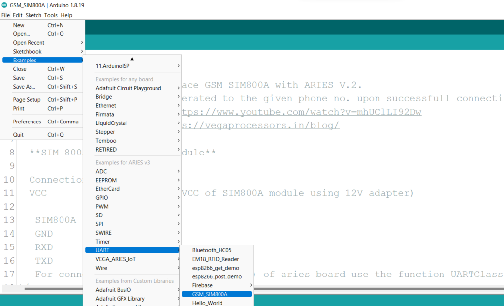
Now, Open Files -> Examples -> Under Examples for ARIES v3 -> UART-> GSM_SIM800A
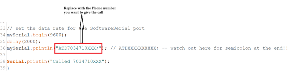
Replace the highlighted part in the below image, with the mobile number which you want to give the test call.
After doing the above step, Finally Upload the code to ARIES v3.0 board
Output
Once the code is uploaded, A call will be generated to the given phone no. upon successfull connection.