Now we are going to learn how we can interface ADXL345 to ARIES v2 Board. The ADXL345 is a low-power, 3-axis MEMS accelerometer module with both I2C and SPI interfaces. The ADXL345 board features an onboard 3.3V voltage regulator and level shifter it simple to interface with microcontrollers.
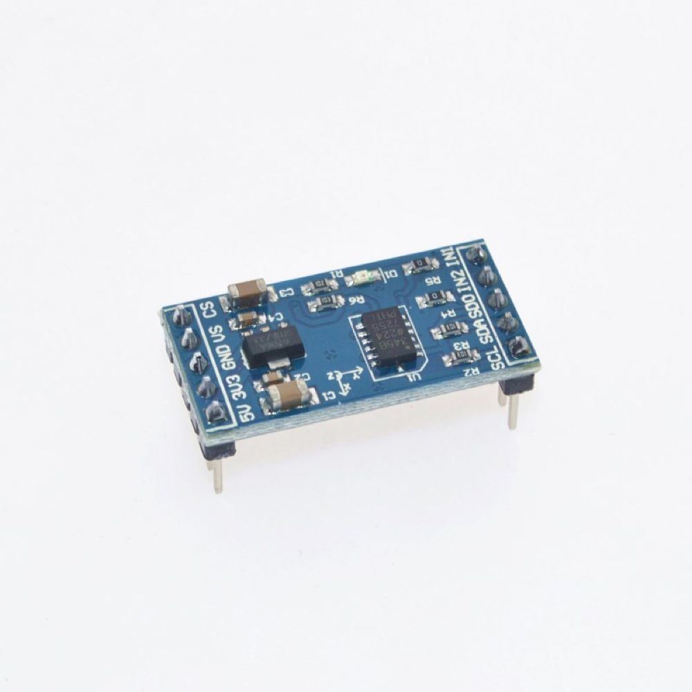
ADXL345 Digital Accelerometer
This ADXL345 Accelerometer module consists of an ADXL345 Accelerometer IC, Voltage Regulator IC, Level Shifter IC, resistors, and capacitors in an integrated circuit. Different manufacturers use different voltage regulator ICs. ADXL345 IC from Analog Devices is the brain of this module. The ADXL345 is a small, thin, low-power, complete 3-axis accelerometer with signal conditioned voltage outputs. The product measures acceleration with a minimum full-scale range of ±16g.
The basic structure of the accelerometer consists of fixed plates and moving plates. When the acceleration is applied on an axis capacitance between fixed plates and moving plates is changed. This results in a sensor output voltage amplitude, which is proportional to the acceleration.
Circuit Diagram
ADXL345 Accelerometer module consists of 8 pins. Using the ADXL345 module with a microcontroller is very easy. Connect VCC and GND pins to 3.3V and GND pins of Microcontroller. Also, connect SCL to I2C1-SCL and SDA to I2C1-SDA of ARIES v2 Board.
Now, for powering up and programming the code into the ARIES v2 Board, we have to connect a micro USB type B (common data cable, used for mobile charging and data transfer) in the UART0 port of the ARIES v2 Board, to a Laptop/Desktop/PC with preinstalled VEGA SDK and Toolchain.
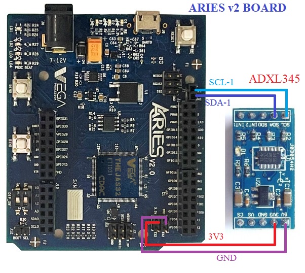
| ADXL345 | ARIES v2 Board |
| 3V3 | +3V3 |
| GND | GND |
| SCL | SCL-1 |
| SDA | SDA-1 |
Procedure
After setting up the toolchain and SDK path environments, build the example program for the ADXL345 sensor by:
cd vega-sdk/examples/i2c/adxl345_demomake clean command to clean the executable :
make cleanthen use the make command to build it.
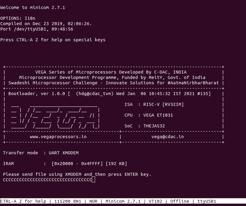
makeNow, we can transfer the built program to the board, before transfer please ensure that you have connected the UART0 connector of the board to the PC.
Open a new terminal and execute the following command.
sudo minicom ariesNow you can see the minicom terminal opened and the board UART terminal is ready.
Use CTRL+A S to enter the file sending menu and select xmodem by pressing Enter.
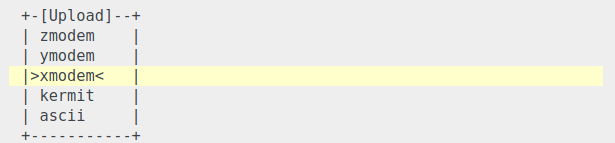
In the next window, with the Space bar select the adxl345_demo.bin file to be transferred, by pressing Enter, the transfer process starts.
Wait until the process is completed. The screen should display how much data has been transferred.
After completing the transfer the Program will start to execute
The output is displayed in the minicom UART terminal:
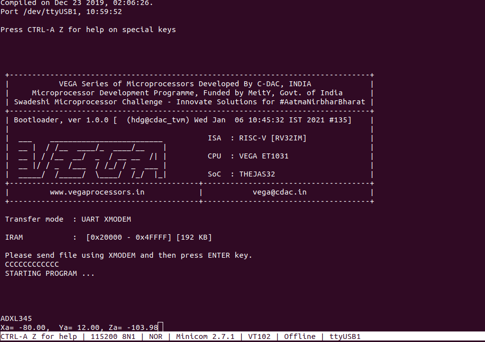
Xa, Ya, Za —> 3-axis accelerometer output
For additional pieces of information:
https://www.analog.com/media/en/technical-documentation/data-sheets/ADXL345.pdf