In this tutorial, you will learn how to interface 8×8 LED Matrix using the MAX7219CNG driver with the ARIES v2 Board. There are two sample programs on 8×8 LED Matrix Interface. The first project vega-sdk/examples/spi/led_dot_matrix_demo is a simple program that runs on the ARIES v2 Board to display an image on the 8X8 LED Matrix. The second project vega-sdk/examples/spi/led_dot_matrix_scroll_demo is an advanced project where scrolling text is displayed on the 8×8 LED Matrix using the ARIES v2 board.
LED displays are often packaged as matrixes of LEDs arranged in rows of common anodes and columns of common cathodes, or the reverse. They can be used to display almost anything. Most modern LED sign boards use various types of matrix boards with controllers.
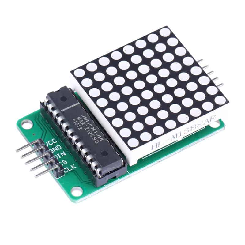
MAX7219CNG
MAX7219CNG is a programmable display driver integrated circuit that is used to control a large array of LEDs while consuming a relatively small number of GPIO pins. It receives input commands via four SPI pins and uses these commands to drive either an 8×8 matrix of LEDs or an eight-digit seven-segment display.
The MAX7219CNG has a bonafide command protocol, built on SPI, where you send a 12-bit packet that encodes both a 4-bit command and an 8-bit value. In this packet, the Most Significant Bits (MSBs), or the ones that are sent first, encode the command, and the Least Significant Bits (LSBs) encode the data. The specific packet is constructed such that
- bits 0-3 encode a command
- bits 4-11 encode the value that should be passed to the command
Circuit Diagram
MAX7219CNG communicates with the ARIES v2 Board via the SPI port. MAX7219CNG is composed of 5 pins. Connect VCC and GND of the MAX7219 dot matrix module to +5V and GND respectively of the ARIES v2 Board. Then connect DIN to SPI0-MOSI, CS to SPI0-SS, and CLK to SPI0-SCLK of the ARIES v2 Board.
Now, for powering up the ARIES v2 board via USB port of a Laptop/Desktop/PC and burning the code into the ARIES v2 board, we have to use a micro USB type B to USB type A cable. The cable should be connected to UART0 port of the ARIES v2 board, and the Laptop/Desktop/PC should be preinstalled with VEGA SDK and Toolchain.
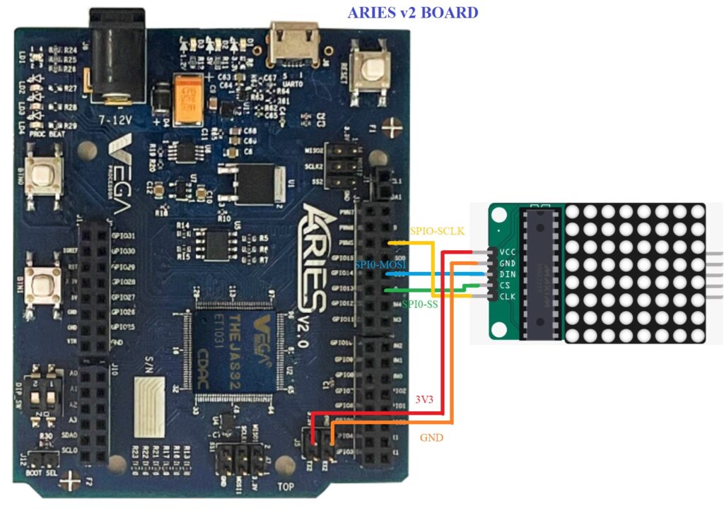
| LED DOT Matrix | ARIES v2 Board |
| VCC | +5V |
| GND | GND |
| DIN | SPI0-MOSI |
| CS | SPI0-SS |
| CLK | SPIO-SCLK |
Procedure
After setting up the toolchain and SDK path environments, build the example program for the MAX7219CNG module by :
choose the below program for displaying an image:
cd vega-sdk/examples/spi/led_dot_matrix_demoor choose the other program which displays scrolling text:
cd vega-sdk/examples/spi/led_dot_matrix_scroll_demomake clean command to clean the executable :
make cleanthen use the make command to build it.
makeNow, we can transfer the built program to the board, before transfer please ensure that you have connected the board UART0 connector to the PC.
Open a new terminal and execute the following command.
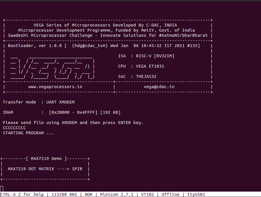
sudo minicom ariesNow you can see the minicom terminal opened and the board UART terminal is ready.
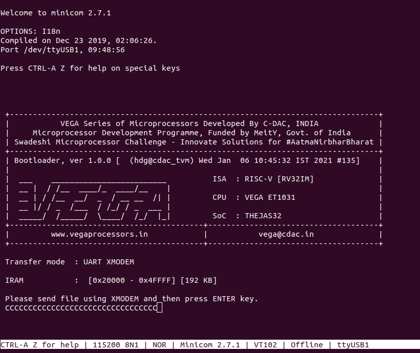
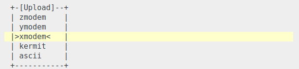
Use CTRL+A S to enter the file sending menu and select xmodem by pressing Enter.
In the next window, with the space bar select the led_dot_matrix_demo.bin file or select the led_dot_matrix_scroll_demo.bin file, to be transferred, by pressing Enter, the transfer process starts.
Wait until the process is completed. The screen should display how much data has been transferred.
After completing the transfer the Program will start to execute
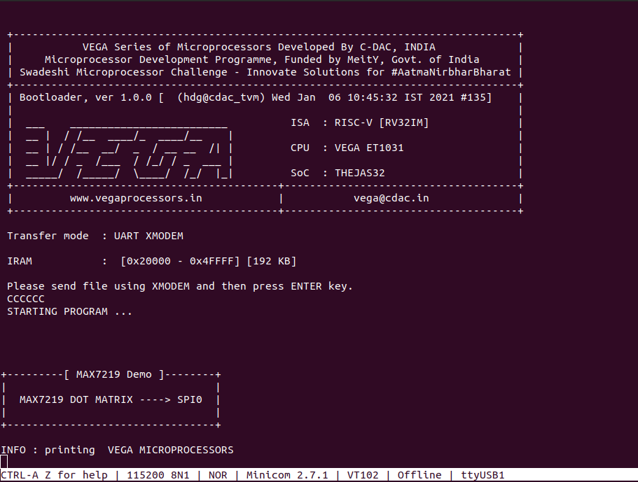
The minicom UART terminal displays the following when the first program is executed:
The minicom terminal displays the following when the second program is executed: