In this tutorial, we will see how we can interface two channel relay module with ARIES v3board. The two Channel Relay Module is used to control high voltage, high current load such as motor, solenoid valves, lamps and AC load.
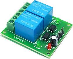
2 Channel Relay
A relay is an electromagnetic switch operated by a relatively small current that can control much larger current. The two-channel relay module comprises of components that make switching and connection easier and act as indicators to show if the module is powered and if the relay is active or not. It uses an electric current to open or close the contacts of a switch. This is usually done using the help of a coil that attracts the contacts of a switch and pulls them together when activated, and a spring pushes them apart when the coil is not energised.
Prerequisites
- Windows 10 or above/Linux (64 bit)
- Arduino IDE
- VEGA ARIES Board support package
Components Required
- ARIES v3.0 Board
- USB type C to USB type A cable
- Two-channel Relay Module
- Jumper Wires
Note: All of the following boards can be used for this project
Circuit Diagram
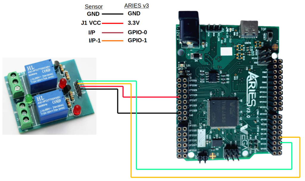
| Relay | ARIES V2 board |
| J1 VCC | 3.3V |
| I/P | GPIO0 |
| G | GND |
| I/P1 | GPIO-1 |
Procedure
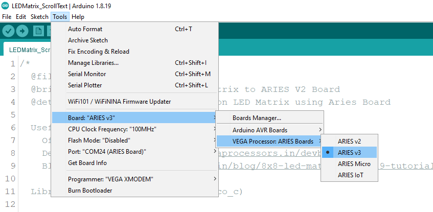
Open and set up the Arduino IDE as described in Getting Started with ARIES v3.0.
- Make sure you have selected ARIES v3 Board from Tools -> Board -> VEGA Processor: ARIES Boards -> ARIES v3
- Select Programmer as VEGA XMODEM from Tools -> Programmer -> VEGA XMODEM
- Also select appropriate port from Tools -> Port -> COM* (ARIES Board)
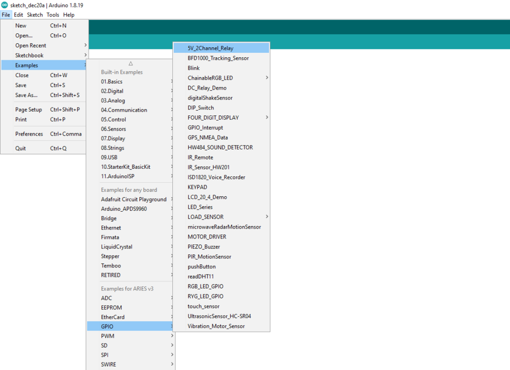
Now, Open Files -> Examples -> Under Examples for ARIES v3 -> GPIO-> 5V_2Channel_Relay
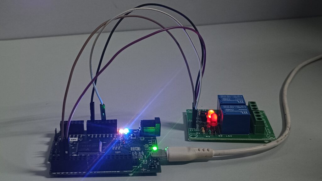
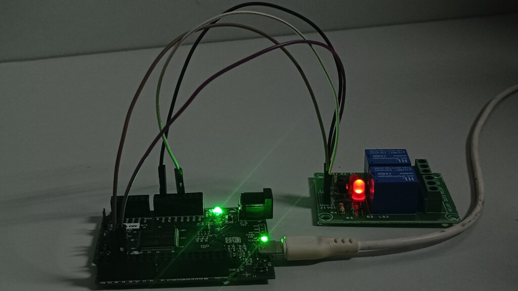
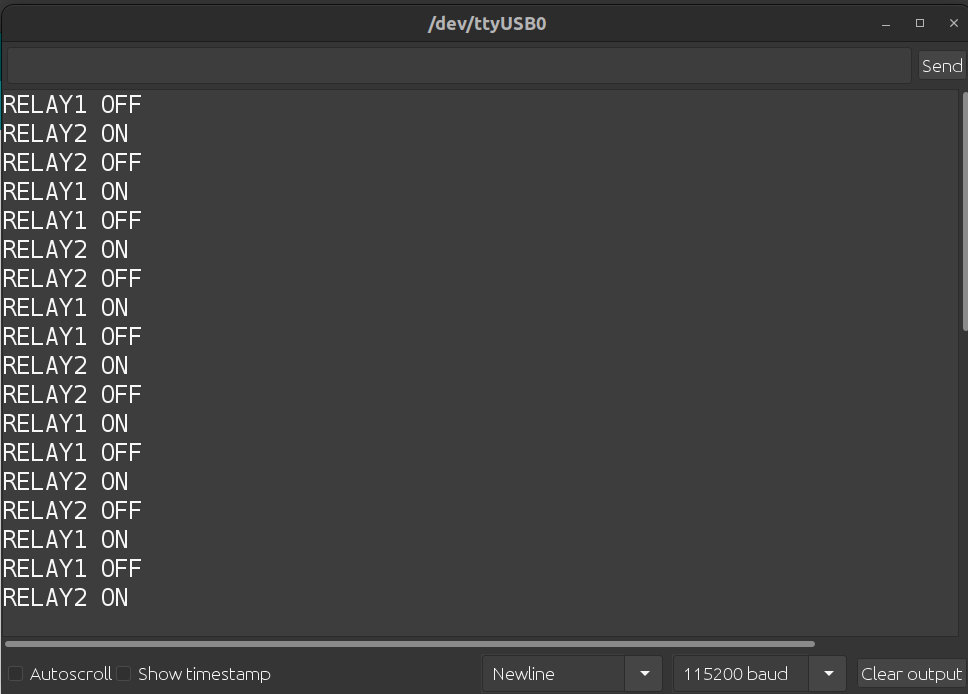
Output
The two LEDs on the relay module will ON/OFF when the Relay is switching. Open the serial monitor at 115200 baud rate to view the relay status as “Relay ON” or “Relay OFF”.