
The term “RYG LED” typically refers to a tri-color LED that can emit three different colors: Red (R), Yellow (Y), and Green (G). These types of LEDs are commonly used in traffic signals, status indicators, visual feedback displays and various electronic devices where multiple colors need to be displayed. Some RYG LEDs can be used with PWM to control the brightness of each color independently, allowing for color mixing effects. By learning how to control an RYG LED with an ARIES board, you can add colorful visual cues to your electronics projects and create captivating light effects.
COMPONENTS NEEDED:
- ARIES v3 Microcontroller
- RYG LED
- Jumper wires
Note: All of the following boards can be used for this project
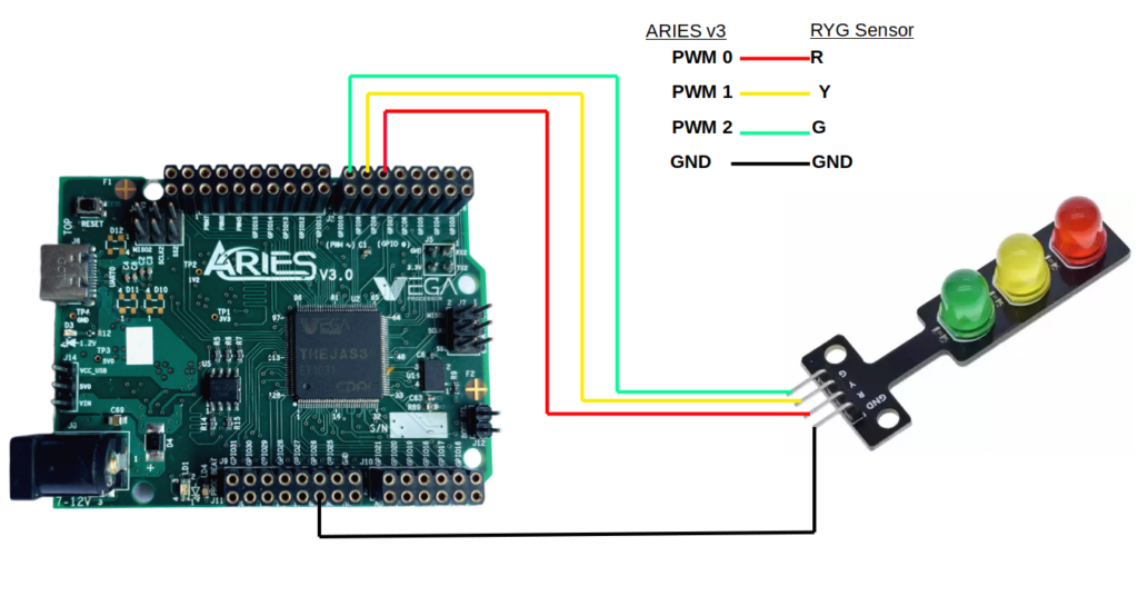
Connections:
| RYG LED | ARIES V3 board |
| GND | GND |
| R | PWM-0 |
| Y | PWM-1 |
| G | PWM-2 |
Now, for powering up the ARIES v3 board via the USB port of a Laptop/Desktop/PC and burning the code into the ARIES v3 board, we have to use a USB type C to USB type A cable. The cable should be connected to UART-0 port of the ARIES v3 board, and the Laptop/Desktop/PC should be preinstalled with Arduino IDE and VEGA ARIES boards of latest version.
Circuit Diagram:
Procedures:
Open Arduino IDE
Go to Tools -> Board -> VEGA Processor ARIES Boards -> Select ARIES v3
Select Flash Mode -> Enabled
Go to Tools -> Programmer -> Select VEGA FLASHER
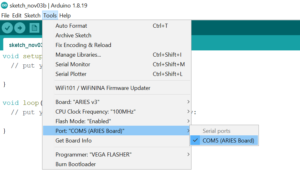
Connect the ARIES v3 board to PC
Go to Tools -> Port -> Select the appropriate port
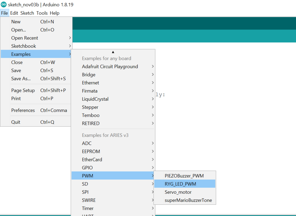
Open File -> Examples -> Examples for ARIES v3 -> PWM -> Open RYG_LED_PWM example
Verifyand Upload the code
Output:
Once you’ve completed the code, upload it to your ARIES v3.0 board using the Arduino IDE. Watch as the RYG LED comes to life and showing different color patterns you’ve programmed. The intensity of the light will be varying for each of the 3 LEDs available which you can observe.
