In this tutorial we will see how we can use DIP Switches in our application.
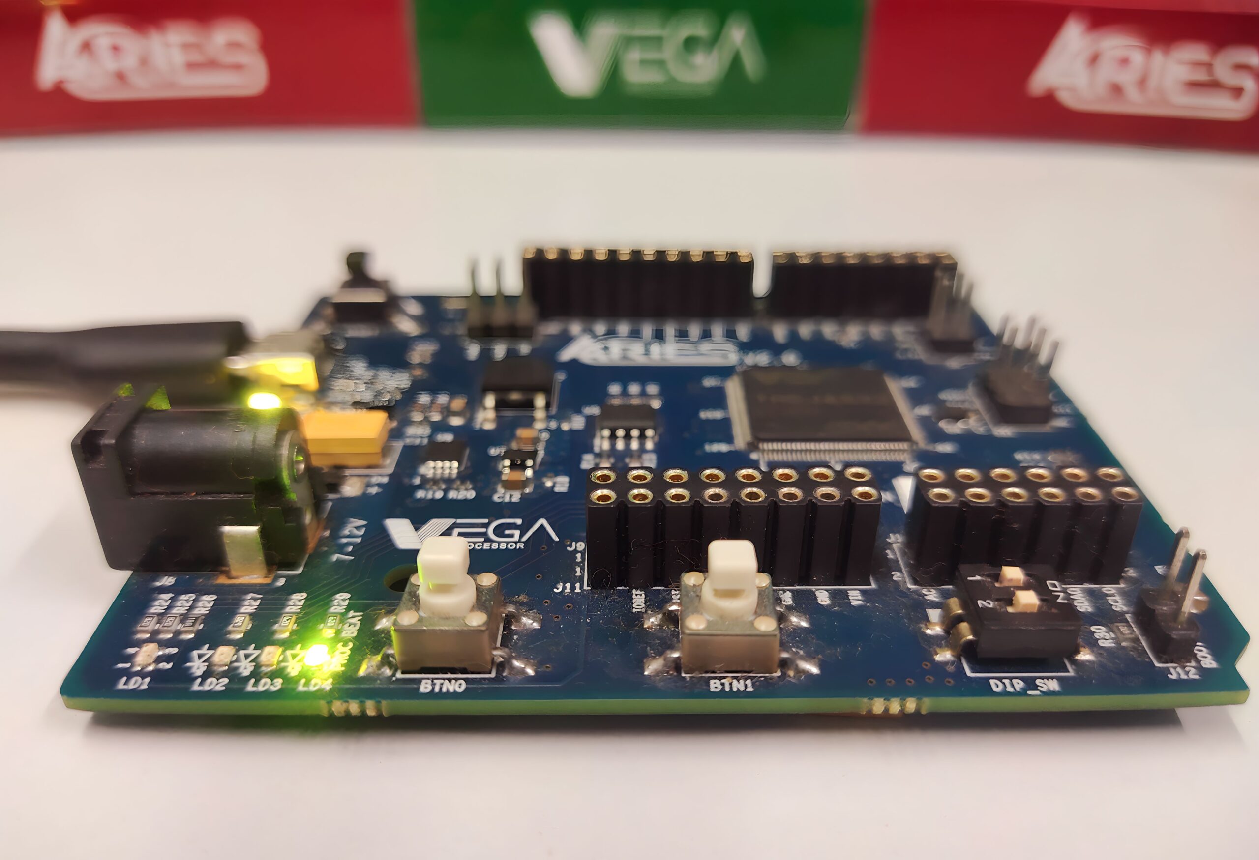
ARIES v2.0
The ARIES v2.0 is a fully indigenous and a “Made in India” product to get started with basic microprocessor programming and embedded systems. This board is built upon a RISC-V ISA compliant VEGA Processor with easy-to-use hardware and software. For more details about ARIES v2.0 boards please refer to the ARIES development boards and Ecosystem.

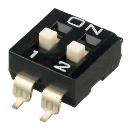
DIP Switches
A DIP (Dual In-Line Package) switch is a small switch in a DIP that is packaged with others in a group to hold configurations and select the interrupt request. It is a set of manual electrical switches, which may refer to the unit as a whole, or to each individual switch, and its position changes the operating mode of a device. ARIES v2.0 has 2 position 2 way electronic DIP switch..
Prerequisites
- Windows 10 or above/Linux (64 bit)
- Arduino IDE
- VEGA ARIES Board support package
Components Required
- ARIES v2.0 Board
- Micro USB type B to USB type A cable
Procedure
Let’s power up the ARIES v2 board via the USB port of a Laptop/Desktop/PC and burning the code into the ARIES v2 board, we have to use a micro-USB type B to USB type A cable. The cable should be connected to UART-0 port of the ARIES v2 board, and the Laptop/Desktop/PC should be preinstalled with Arduino IDE and VEGA ARIES boards of latest version.
- Now, open the Arduino IDE
- Make sure you have selected ARIES v2 Board from Tools -> Board -> VEGA Processor: ARIES Boards -> ARIES v2
- Enable flash mode from Tools -> Flash Mode -> Enabled
- Select Programmer as VEGA FLASHER from Tools -> Programmer -> VEGA FLASHER
- Also select appropriate port, Tools -> Port -> COM* (ARIES Board)

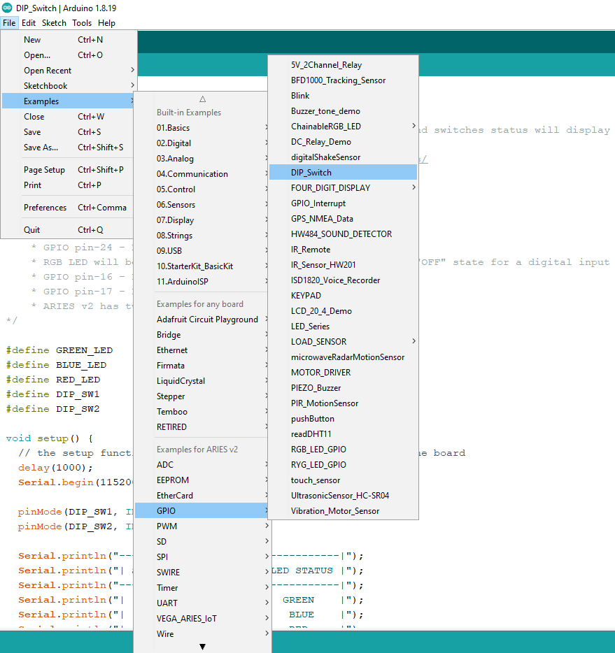
- Open File -> Examples -> Under Examples for ARIES v2 -> GPIO -> DIP_Switch
- Now Upload the code and Open Serial Monitor with 115200 Baudrate.
Output
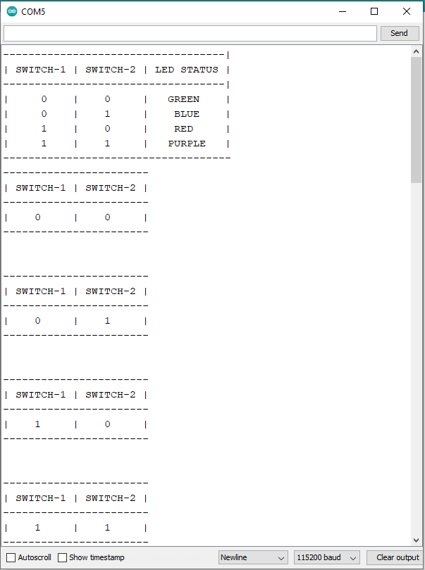
The 2-position DIP Switch on ARIES v2.0 has “ON” written on one side and their number on another side. If we slide switch towards “ON” it will give digital input 0. Once we uploaded the code, slide both DIP switches towards “ON”, in this case both switches will give digital 0 input to the board and Green LED will turn on. Now, slide switch-2 to the other side. In this case switch-1 will give input digital 0 and switch-2 will give digital 1 and Blue LED will turn ON.
In this way maximum 4 combinations are possible as shown below.
| SWITCH-1 | SWITCH-2 | STATUS |
| 0 | 0 | Green LED will turn ON |
| 0 | 1 | Blue LED will turn ON |
| 1 | 0 | Red LED will turn ON |
| 1 | 1 | Purple LED will turn ON |
On serial monitor, we will get current position of both switches.