In this tutorial, we will discuss how to communicate between two ARIES boards with the help of the RS485 (Modbus RTU) serial data communication protocol. We will follow the RS485 master-slave communication method. For demonstration purposes, we will create a project that will ON or OFF a LED connected to a Slave ARIES from Master ARIES by sending some commands through RS485 Module. The master ARIES uses a push button to control the LED attached to the slave device.
MAX485 TTL to RS485 Module
For using RS-485 in ARIES, a module called MAX485 TTL to RS485 which is based on Maxim MAX485 IC is needed as it allows serial communication over long distance.The MAX485 TTL to RS-485 Interface Module allows MCUs to use the RS-485 differential signaling for robust long distance serial communications. ARIES boards doesn’t have any peripherals for Modbus communication. We will use an RS485-based sensor module called MAX485 for communication between two ARIES boards. The MAX485 pin description is given in the following table:
| Pin Name | Description | Function |
| RO | Receiver Output | Connects to a serial RX pin on the microcontroller |
| RE | Receiver Enable | Active LOW. Connects to a digital output pin on a microcontroller. Drive LOW to enable receiver, HIGH to enable Driver |
| DE | Driver Enable | Active HIGH. Typically jumpered to RE Pin. |
| DI | Driver Input | Connects to serial TX pin on the microcontroller |
| VCC | Voltage Common Collector | supply pin |
| A | Data ‘A’ Non-Inverted Line | Used as non-inverting receiver input and inverting driver output |
| B | Data ‘B’ Inverted Line | Used as inverting receiver input and inverting driver output |
| GND | Ground | Ground |
Modbus Protocol
Modbus is a serial communication protocol developed by Modicon published by Modicon in 1979 for use with its programmable logic controllers (PLCs). In simple terms, it is a method used for transmitting information over serial lines between electronic devices. The device requesting the information is called the Modbus Client and the devices supplying information are Modbus Servers.
RS485
Modbus communicates over different types of physical media and they are:
- RS232: serial communication protocol
- RS485: serial communication protocol
- RS422: serial communication protocol
- Ethernet: LAN (Local Area Network) Technology
RS485 is an asynchronous half-duplex serial communication protocol that communicates over devices by using the master-salve method. It can connect a maximum of 32 devices on the same line. RS485 is used more industrially where many devices need to be interconnected together for a system. Advantages of RS485 over RS232 includes, its longer distances (up to 1200 meters), higher data transfer rate (Up to 30Mbps), and allow for multiple devices connection on a single network by using only two wires.
Prerequisites
- Windows 10 or above/Linux (64 bit)
- Arduino IDE
- VEGA ARIES Board support package
Components Required
| Component | Quantity |
| ARIES v3.0 Board | 1 |
| ARIES v2.0 Board | 1 |
| USB type B to USB type A cable | 1 |
| USB type C to USB type A cable | 1 |
| MAX485 TTL to RS485 converter module | 2 |
| Jumper Wires | Many |
| Bread Board | 1 |
| Push Button | 1 |
| LED | 1 |
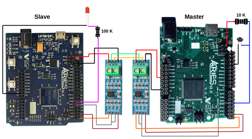
Connection Diagram
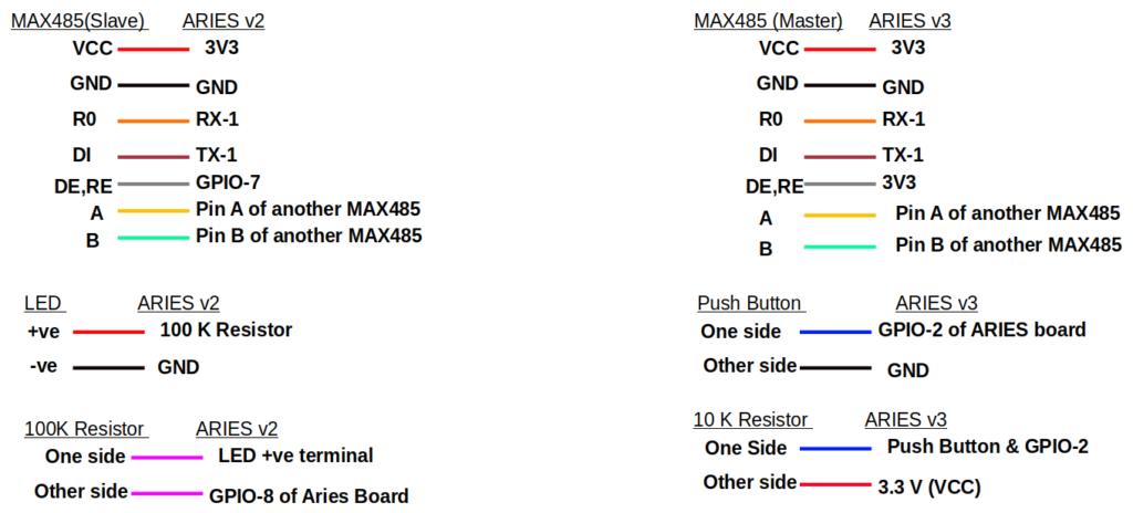
| MAX485 (Master side) | ARIES v3 (Master) |
| RO | RX1 |
| DI | TX1 |
| DE,RE | GPIO-7 |
| VCC | 3.3 V |
| GND | GND |
| A | Pin A of another MAX485 |
| B | Pin Bof another MAX485 |
| Push Button | ARIES v3 (Master) |
| One side | GPIO-2 of ARIES board |
| Other side | GND |
| 10K Resistor | |
| One side | Push Button and GPIO-2 |
| Other side | VCC (3.3 V) |
| MAX485 (Slave side) | ARIES v2 (Slave) |
| RO | RX1 |
| DI | TX1 |
| DE,RE | GPIO-7 |
| VCC | 3.3 V |
| GND | GND |
| A | Pin A of another MAX485 |
| B | Pin Bof another MAX485 |
| LED | ARIES v2 (Slave) |
| +ve | 100 K Resistor |
| -ve | GND |
| 100K Resistor | |
| One side | LED +ve terminal |
| Other side | GPIO-8 of ARIES board |
Procedure
1. Master Side:
Open and set up the Arduino IDE as described in Getting Started with ARIES v3.0.
Check whether the ARIES v3 board, BOOT-SEL pin is shorted or not
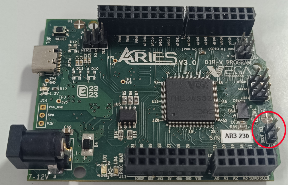
ARIES v3 board with BOOT SEL pin not shorted

ARIES v3 board with BOOT SEL pin shorted
- If
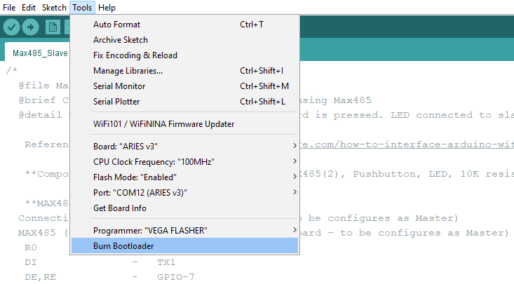
BOOT-SEL jumper (J12) is not shorted : - Click on Tools – Burn Bootloader and wait for the “uploading completed” message in IDE
- Once the program got uploaded, Connect the BOOT SEL pin in ARIES board using a shorting jumper / Female-Female connector (NOTE: Shorting jumper is always preferred. This is a one time step only.)
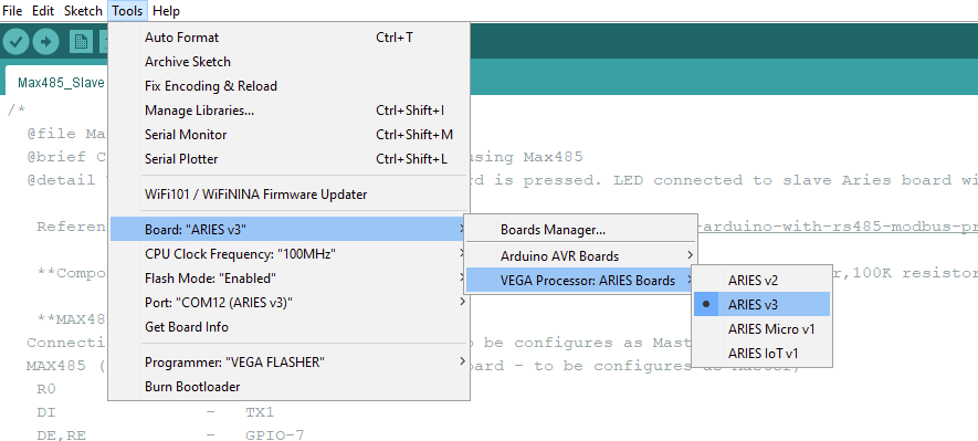
- Make sure you have selected ARIES v3 Board from Tools -> Board -> VEGA Processor: ARIES Boards -> ARIES v3
- Select Flash Mode -> Enabled
- Select Programmer as VEGA FLASHER from Tools -> Programmer -> VEGA FLASHER
- Also select appropriate port from Tools -> Port -> COM* (ARIES v3)

If
- BOOT-SEL jumper (J12) is already shorted :
- Select Flash Mode -> Enabled
- Make sure you have selected ARIES v3 Board from Tools -> Board -> VEGA Processor: ARIES Boards -> ARIES v3
- Select Programmer as VEGA FLASHER from Tools -> Programmer -> VEGA FLASHER
- Also select appropriate port from Tools -> Port -> COM* (ARIES v3)
- Above mentioned steps are needed to flash the program to ARIES board permanently.
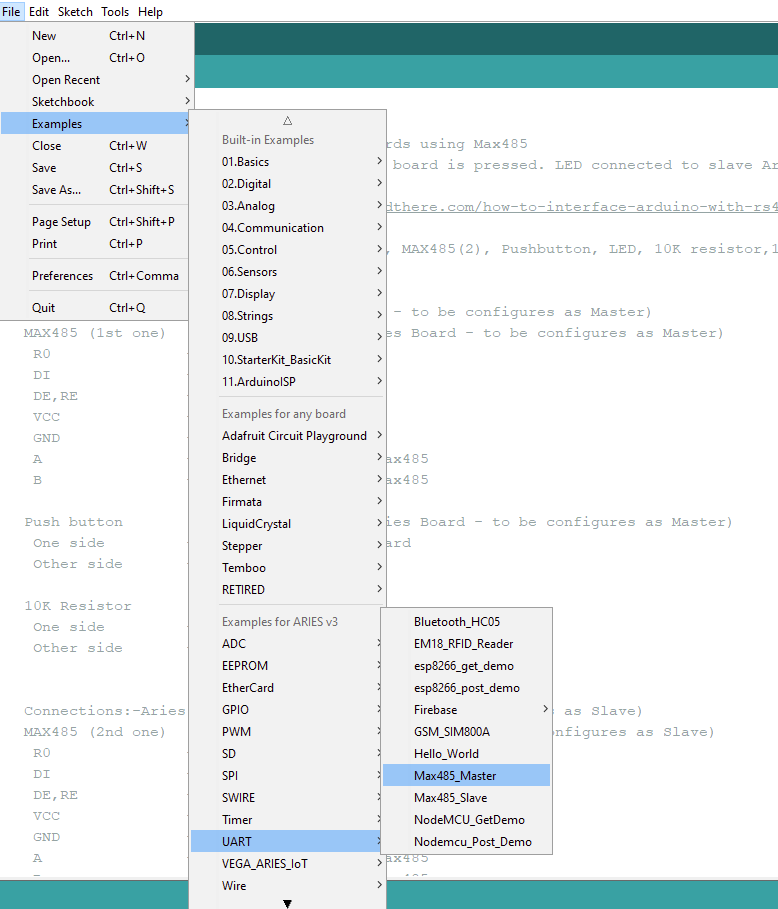
Now, Open Files -> Examples -> Under Examples for ARIES v3 -> UART-> Max485_Master
Upload the code in ARIES v3 board which is set as Master in this example.
2. Slave side
Open and set up the Arduino IDE as described in Getting Started with ARIES v2.0
Let’s power up the ARIES v2 board via the USB port of a Laptop/Desktop/PC and burning the code into the ARIES v2 board, we have to use a micro-USB type B to USB type A cable. The cable should be connected to UART-0 port of the ARIES v2 board, and the Laptop/Desktop/PC should be preinstalled with Arduino IDE and VEGA ARIES boards of latest version.
- Now, open the Arduino IDE
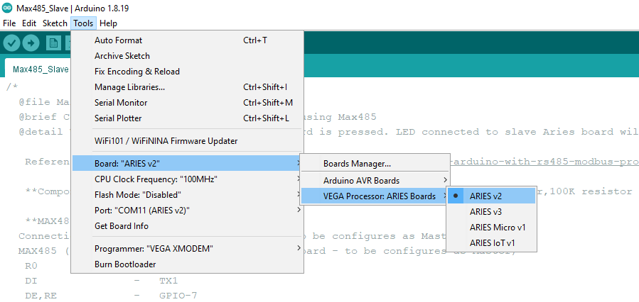
- Make sure you have selected ARIES v2 Board from Tools -> Board -> VEGA Processor: ARIES Boards -> ARIES v2
- Select Programmer as VEGA XMODEM from Tools -> Programmer -> VEGA XMODEM
- Also select appropriate port, Tools -> Port -> COM* (ARIES v2)
Now, Open Files -> Examples -> Under Examples for ARIES v3 -> UART-> Max485_Slave
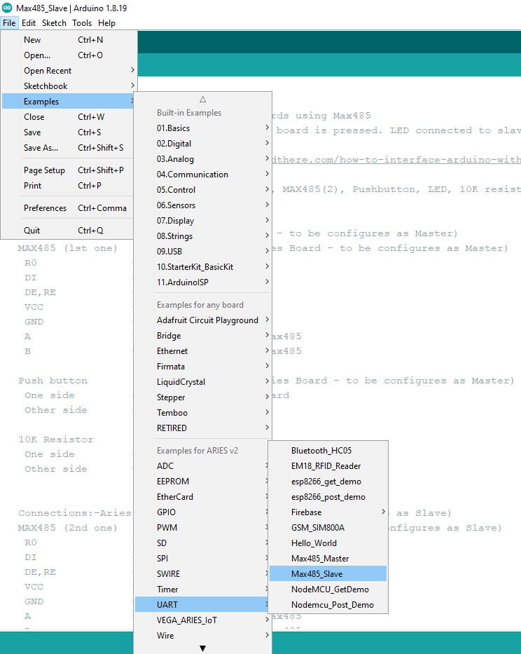
Finally Upload the code in ARIES v2 board.
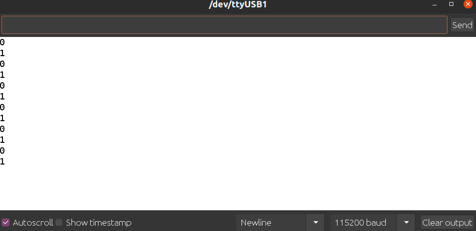
Output
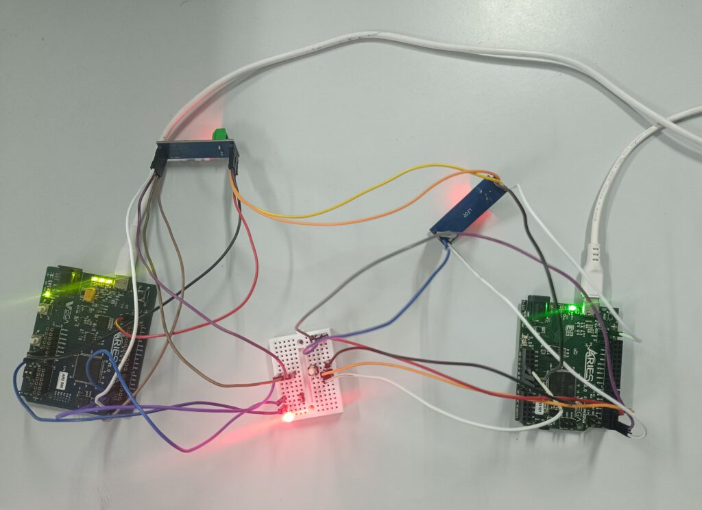
In this sketch, the slave ARIES (ARIES v2) receives the command from the master (ARIES v3) through the MAX485 module by using the RS485 protocol. In Master device we connected a push button and in slave device we connected an LED. If the slave (ARIES v2) receives command “1” then LED will Turn OFF and print “1” to the Arduino IDE serial monitor or, if slave receives command “0” then LED will turn ON and print “0” to the serial monitor.