In this tutorial, we will see how to control Internal LED in ARIES v3.0 board using Alexa App
We need to interface the ESP 01 WiFi Module with ARIES v3 Board to enable Wi-Fi on ARIES v3 boards. The ESP 01 is a low-cost Wi-Fi microchip, with a full TCP/IP stack and microcontroller capability. This small module allows microcontrollers to connect to a Wi-Fi network and make simple TCP/IP connections using Hayes-style commands.
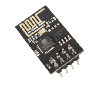
ESP-01 Wi-Fi Module
ESP8266 (ESP 01) is a highly integrated chip designed for the needs of a new connected world. It offers a complete and self-contained Wi-Fi networking solution allowing it to either host the application or to offload all Wi-Fi networking functions from another application processor. ESP 01 has powerful on-board processing and storage capabilities that allow it to be integrated with the sensors and other application-specific devices through its GPIOs with minimal development up-front and minimal loading during runtime.
Its high degree of on-chip integration allows for minimal external circuitry. It is designed to occupy a minimal PCB area.
Prerequisites
- Windows 10 or above/Linux (64 bit)
- Arduino IDE
- VEGA ARIES Board support package
Components Required
- ARIES v3.0 Board
- USB type C to USB type A cable
- ESP 01 Wi-Fi module
- Jumper Wires
Circuit Diagram
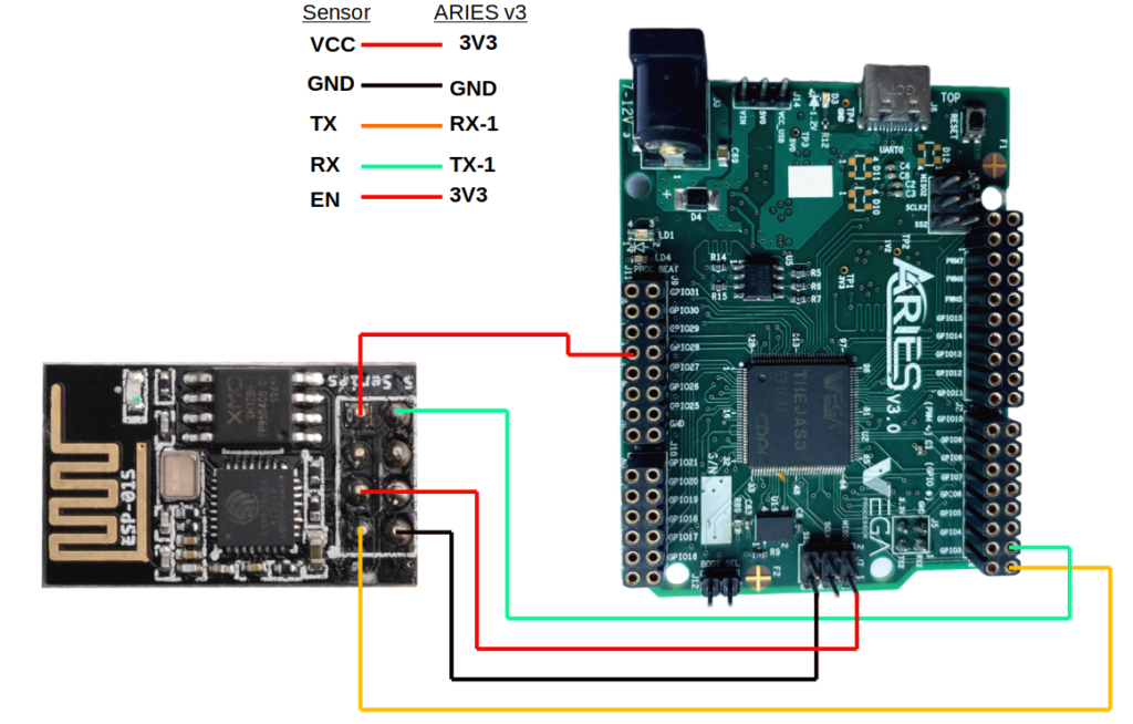
| ESP8266 WiFi Module | ARIES v3 Board |
| VCC | +3V3 |
| GND | GND |
| RXD | TX1 |
| TXD | RX1 |
| *EN | 3V3 |
*Note: Connection of EN pin in ESP to VCC (3V3) of ARIES board is optional.
Procedure
We have to configure the Adafruit IO cloud server before uploading the program to ARIES microcontroller.
Follow the below steps for configuring Adafruit IoT cloud platform
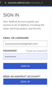
- SIGN UP on Adafruit from Adafruit IO if you doesn’t have an account. If you have Adafruit account use SIGN IN option and login with your credentials.
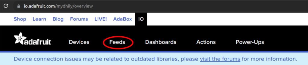
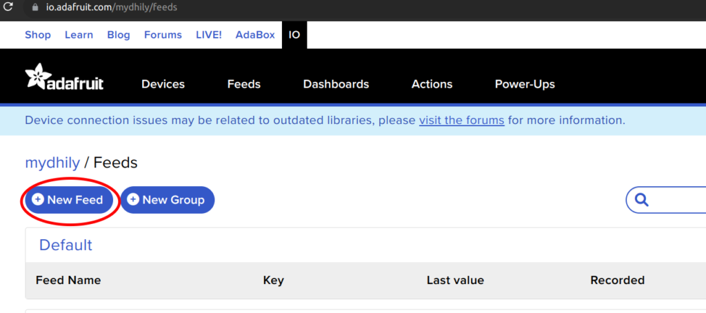
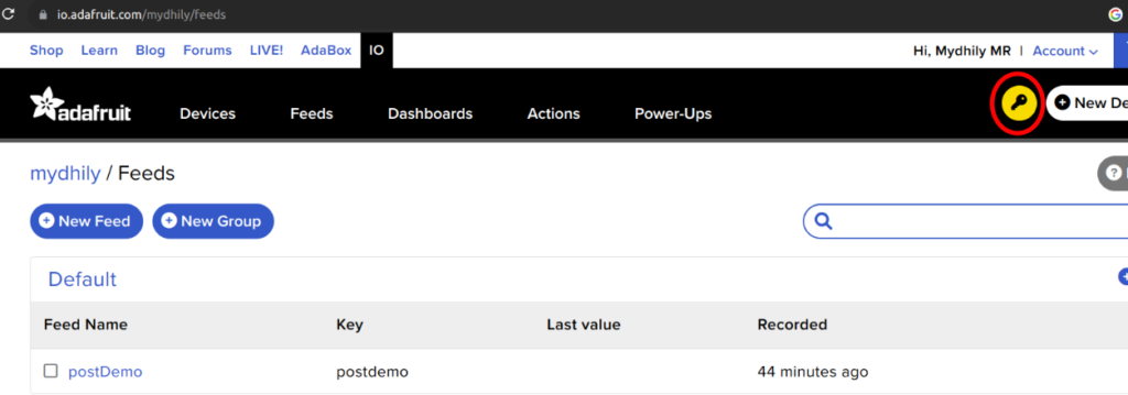
- Click on feeds menu
- Once the feed menu is opened, Click on New feed
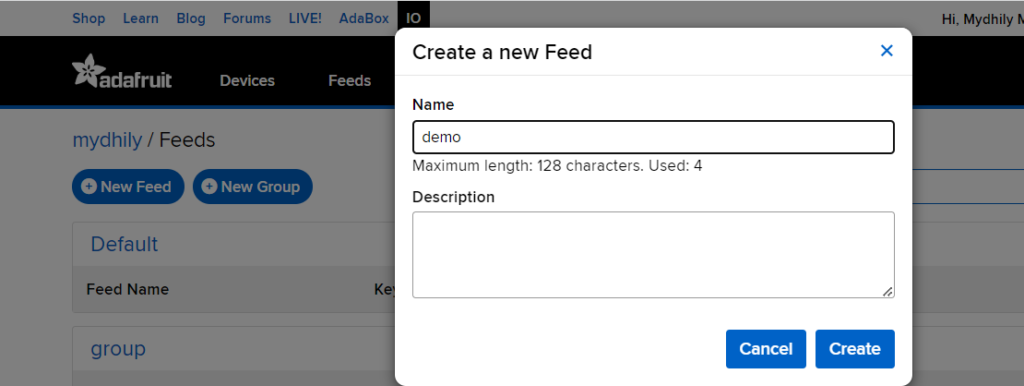
- Create a new feed by giving any feed name. Here we have used “demo” as the feed name. You can give any feed name and Click on Create
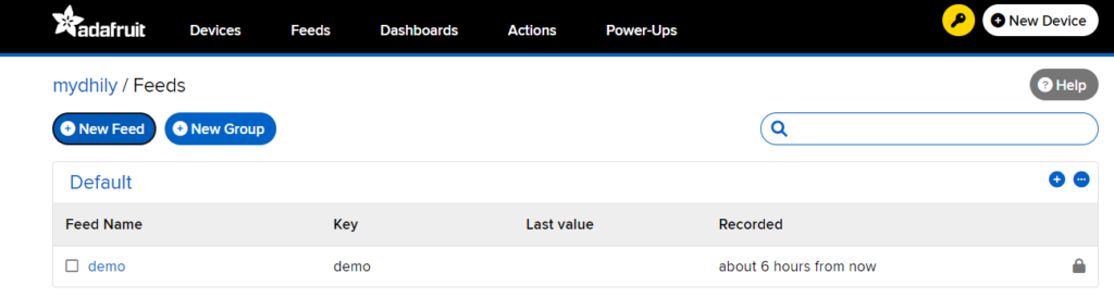
- Now you can see the feed has been created as follows.
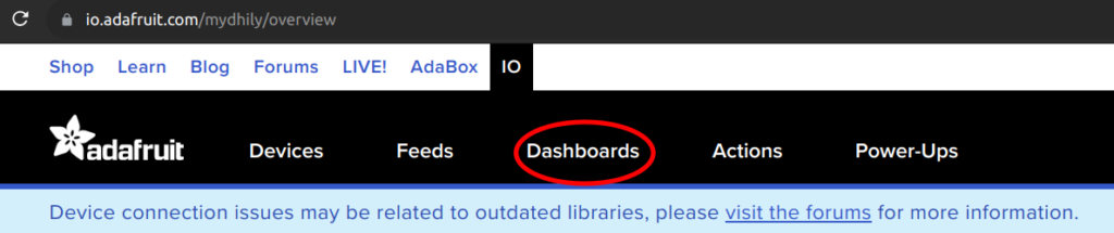
- Now click on Dashboards menu
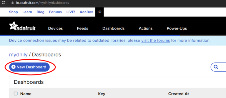
- Click on New Dashboard for creating a dashboard
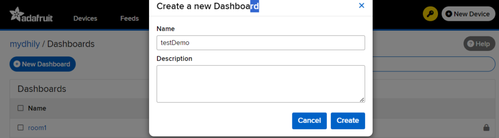
- Give any Dashboard name you like. Here we have given “testDemo” as dashboard name and click on Create
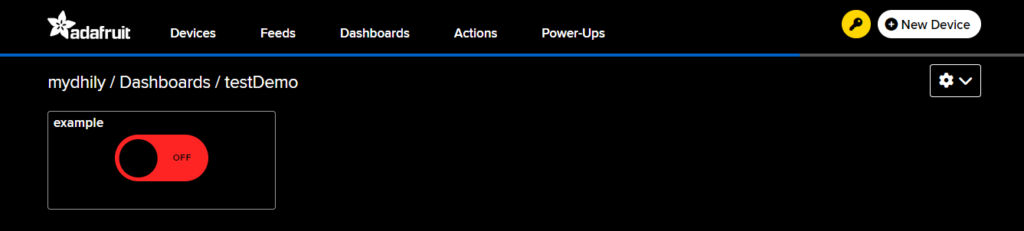
Now you can see the dashboard has been created as follows.
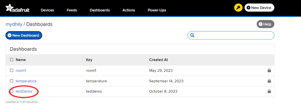
- Click on the Dashboard name you created, to open the dashboard.
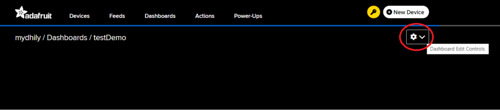
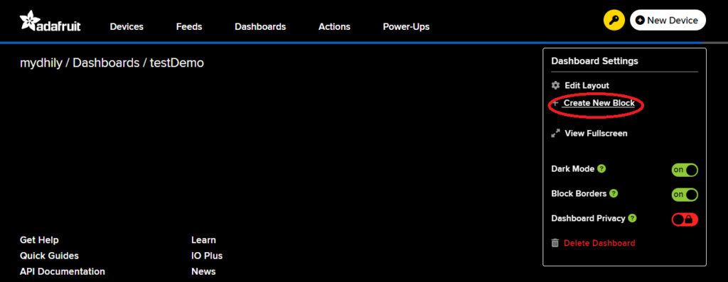
- Once you enter inside the dashboard you created, you can see a black page as follows. Click on the gear icon on the top right
- This will open up a menu as shown in the below figure. Click on Create New Block
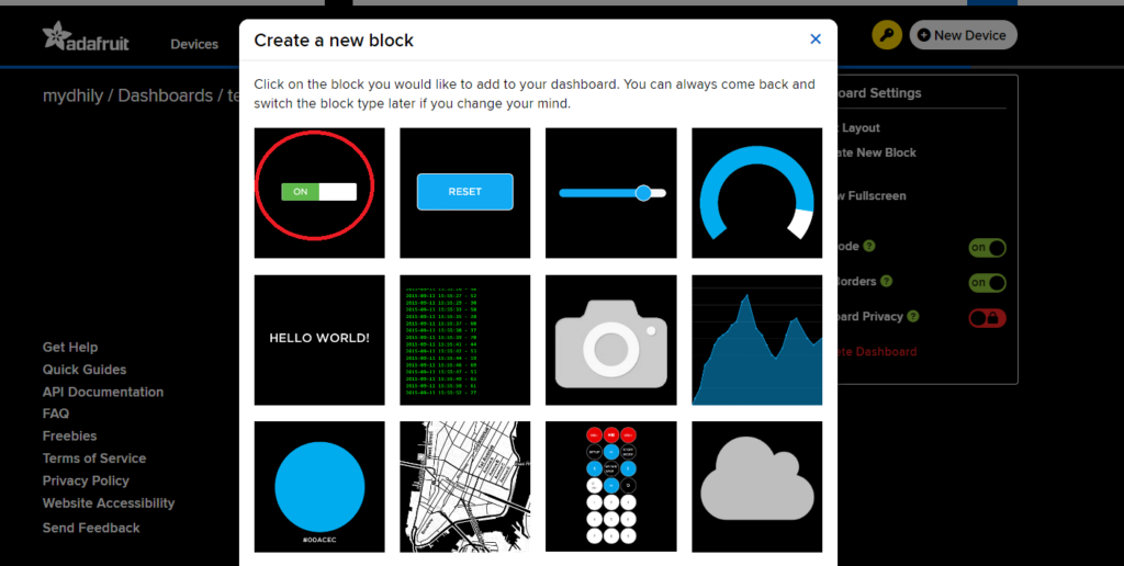
You can see the available blocks. Here we will be using the toggle block to control the LED ON/OFF functionality.
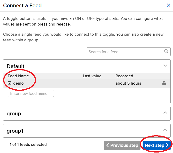
- In the next step, Tick Mark the checkbox to link your feed with the dashboard and click on NEXT STEP
- Give a block title for your selected block. Give Button on value as “1” and Button off value as “0” and click on Create Block.
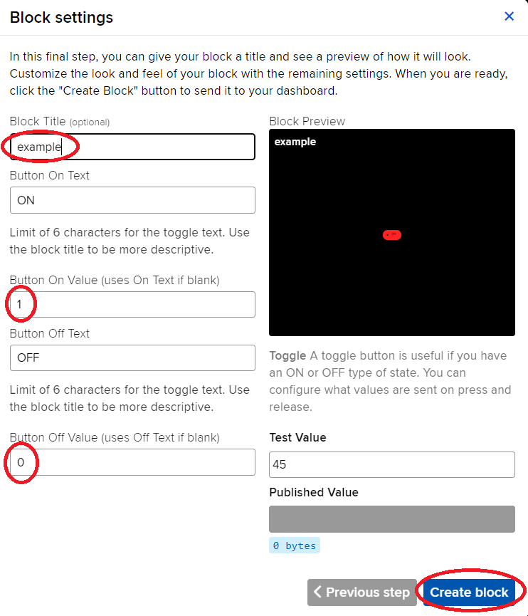
- Now the block has been created.
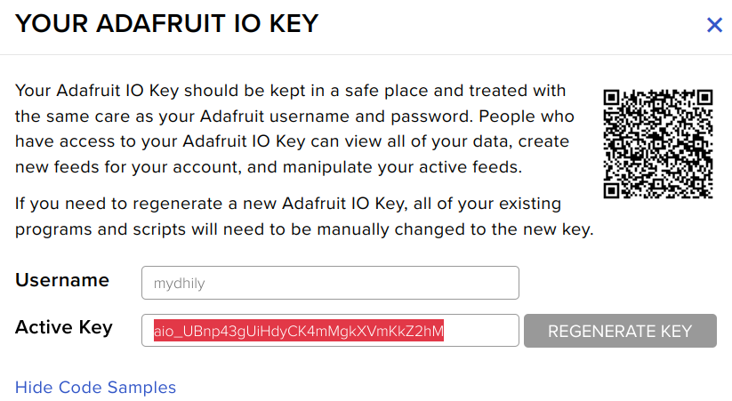
- Click on the yellow key icon to Copy the Adafruit API key (Active Key) to replace the key in the Arduino code.
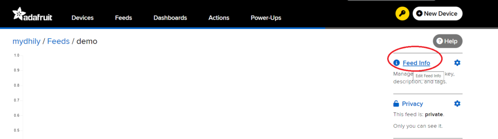
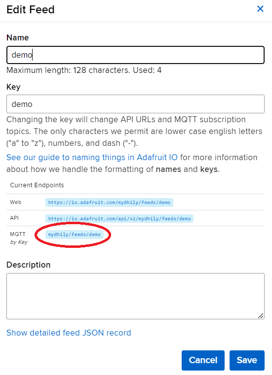
- Click on feed -> Feed info. Copy the MQTT key to replace in the URL portion in the Arduino code
Procedure
Open and set up the Arduino IDE as described in Getting Started with ARIES v3.0.
- Make sure you have selected ARIES v3 Board from Tools -> Board -> VEGA Processor: ARIES Boards -> ARIES v3
- Select Tools -> Flash Mode -> Enabled
- Select Programmer as VEGA FLASHER from Tools -> Programmer -> VEGA FLASHER
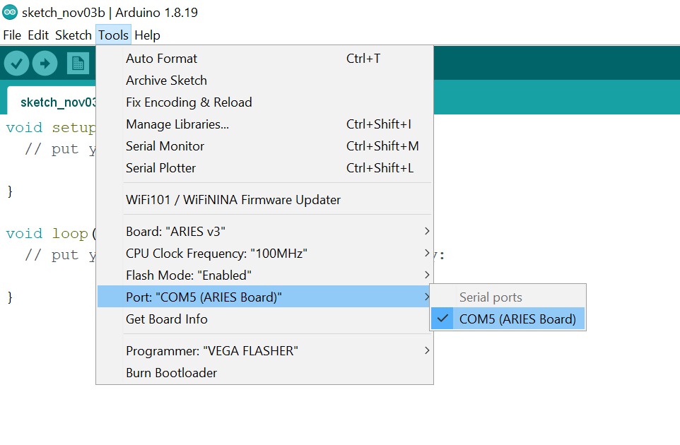
- Also select appropriate port from Tools -> Port -> COM* (ARIES Board)
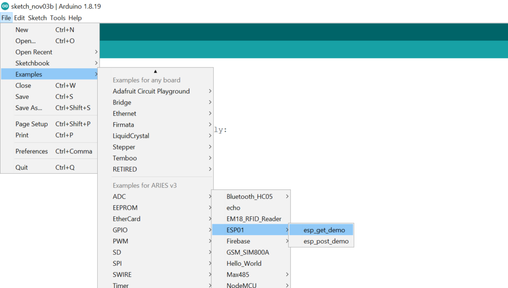
- Now, Open Files -> Examples -> Under Examples for ARIES v3 -> UART-> ESP01 -> esp_get_Demo
- Change the credentials on the code as shown in the image
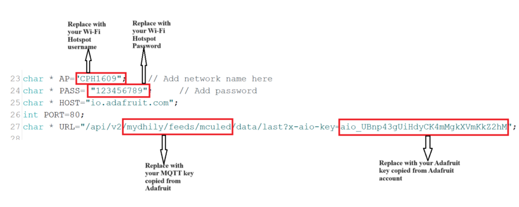
Once the hotspot name, hotspot password,KEY and URL has been replaced with your’s, the procedure is completed.
Finally, Upload the code to ARIES v3 Board and then open the serial Monitor to check AT commands status.
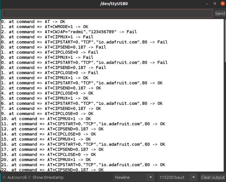
Once all the AT commands are OK, then the data can be sent from the Adafruit cloud platform. You can open the dashboard you created in Adafruit to change the real time data in Adafruit server as shown in the below images. In the example program given, we are changing the toggle led button in Adafruit server to ON and OFF. When the Toggle led button is ON, the inernal LEDs in the ARIES board will turn on, and when the Toggle LED button is OFF the internal LEDs in the ARIES board will turn OFF.
Turn ON/OFF the toggle led button in Adafruit server and wait for few seconds to view the internal LED change in the ARIES board.
If you completed upto this portion, it means you have integrated the cloud control with ARIES board, Now we need to configure Alexa for working with ARIES boards.
Configuring Alexa for LED Control
Following things are necessary for Alexa integration:
- Amazon Account with email id added
- Amazon Account Username & Password
- Adafruit Account
- Alexa app (Download from Googlestore)
- Go to https://ifttt.com

- Click on Get Started for sign up if you don’t have an account. Sign up & Log in

It is preffered to have same email id to be used in ifttt.com, adafruit.io and your amazon account for easy integration.
- Choose your device & click on Continue

- Skip Trial & Click on Get started

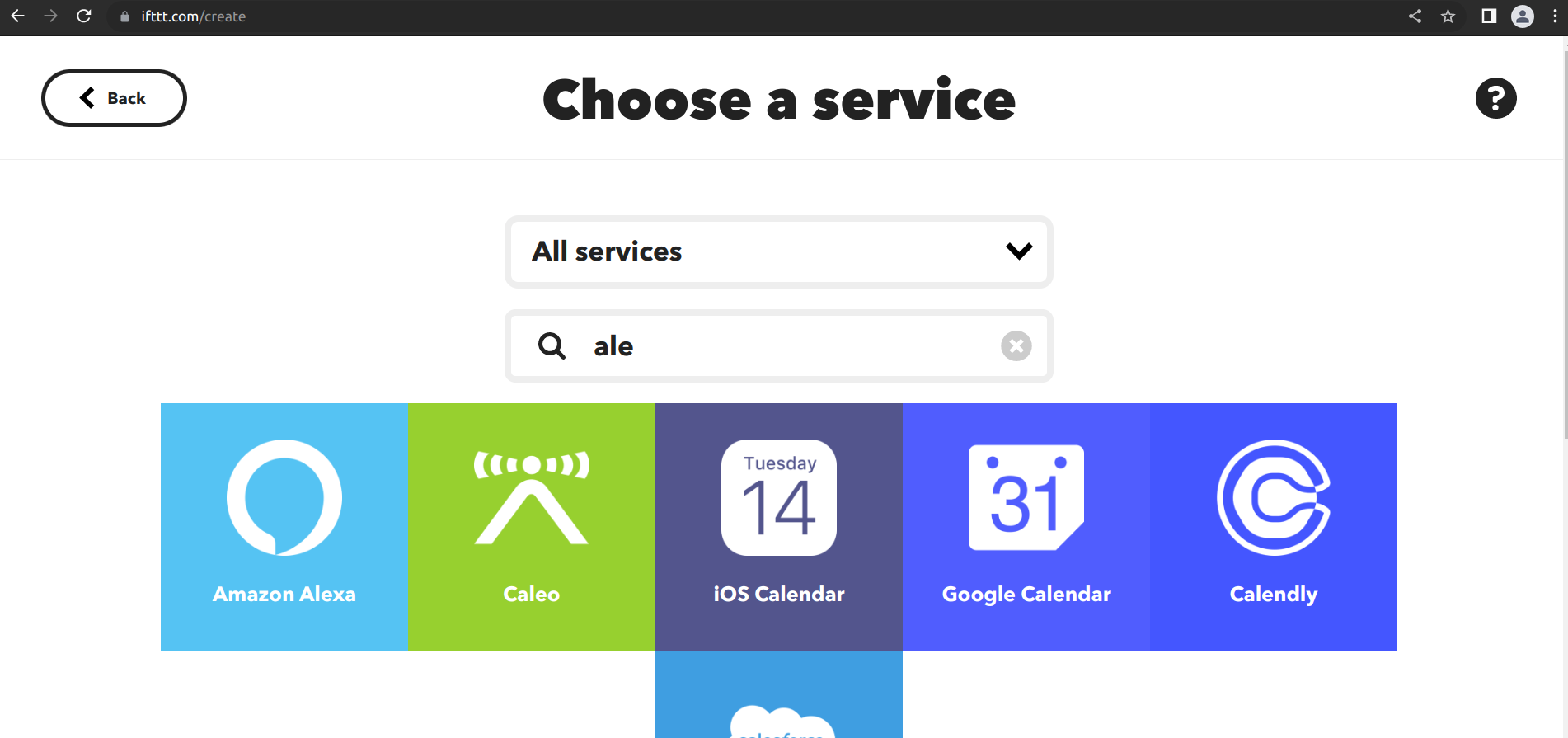
- Search Alexa in Explore

- Click on Amazon Alexa

- Connect with your Amazon Account by clicking on Connect

- Give Amazon Account credentials in the below step

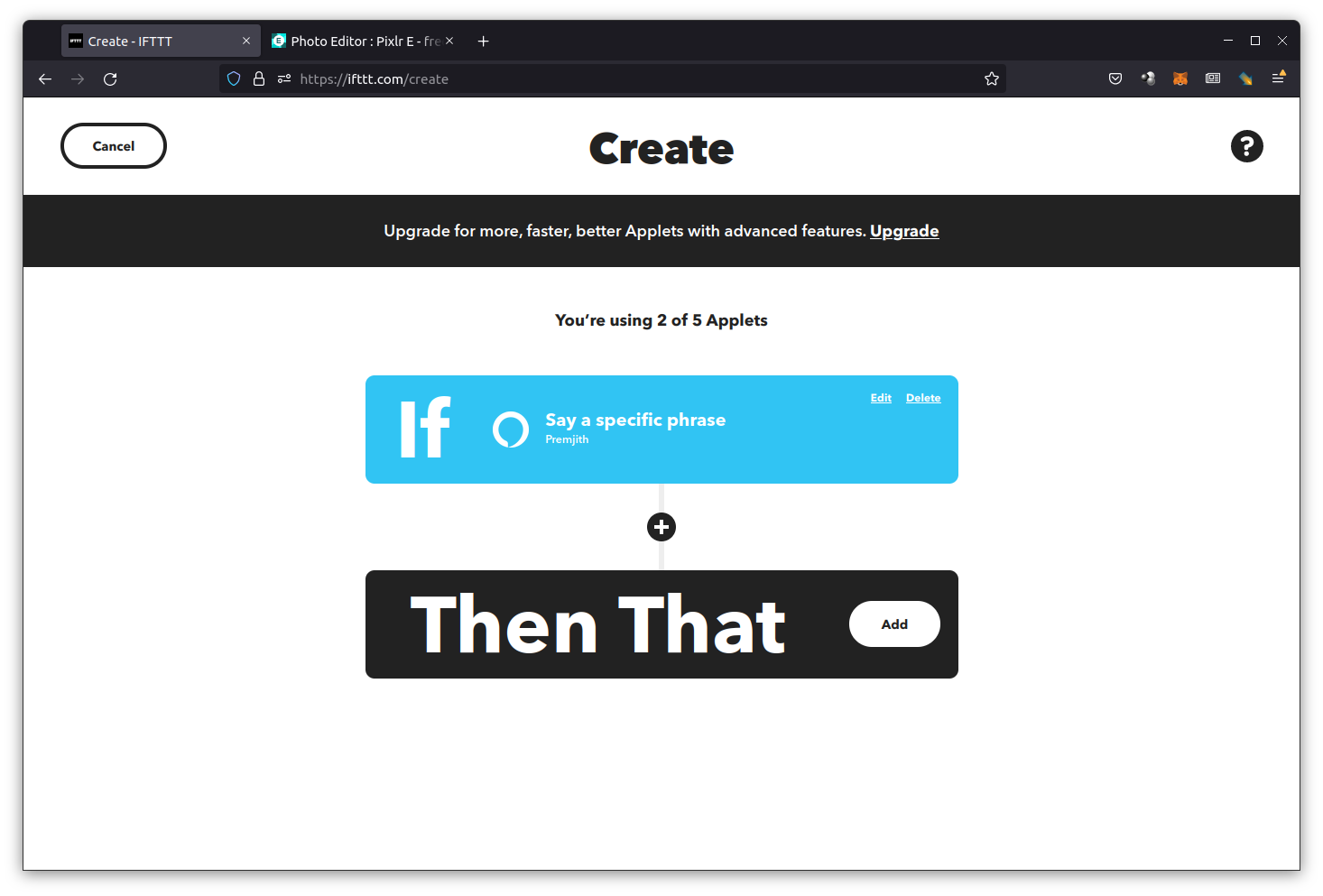
- Click on Create

- Click on Add in If This option.

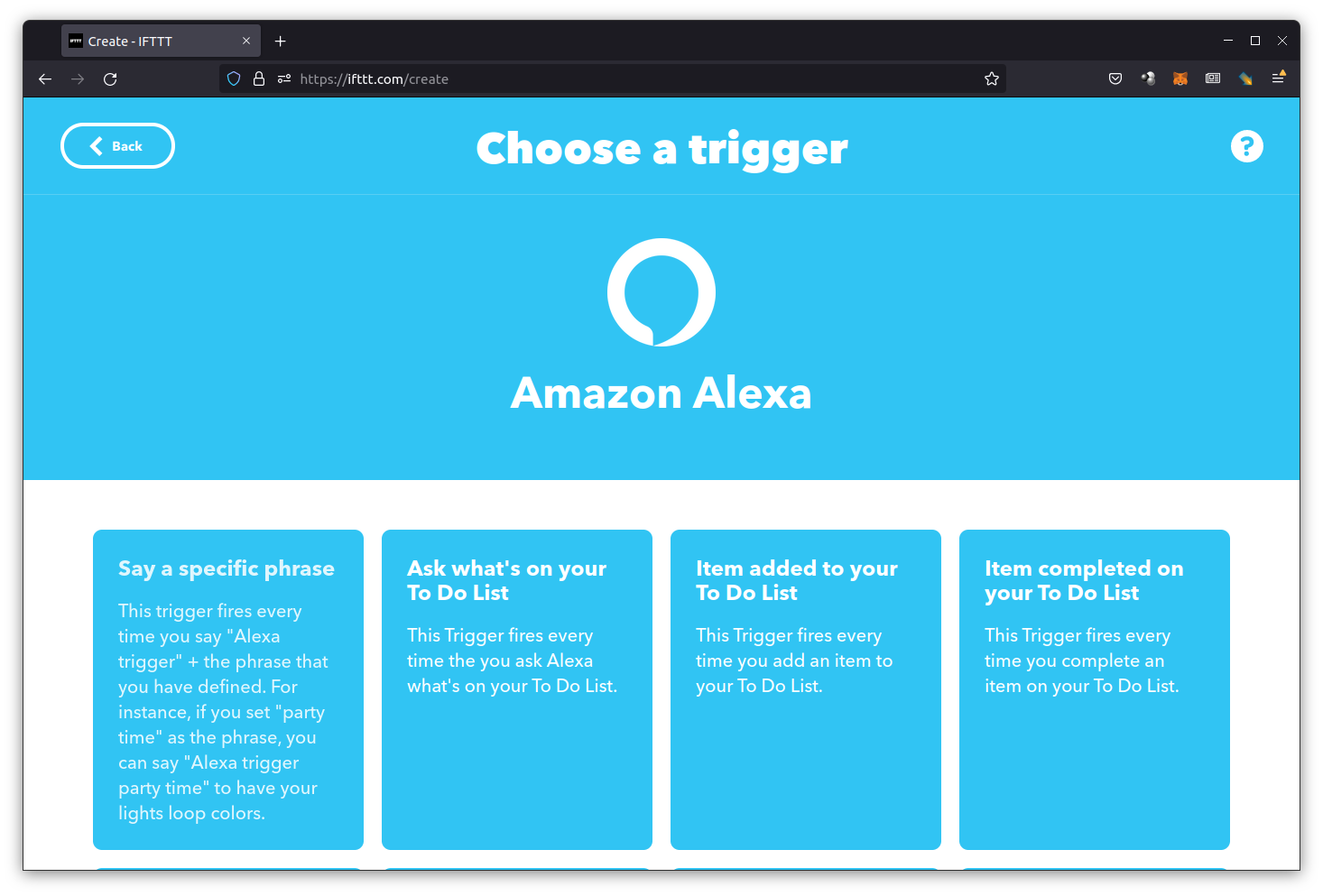
- Search for Alexa & Select Alexa
- Select “Say a specific phrase”
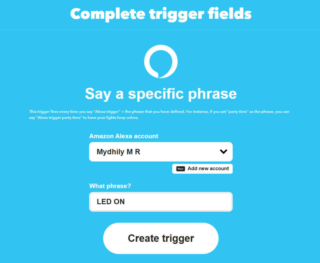
- Enter a custom phrase and create trigger
- Click on Add button in Then That option
- Search for adafruit
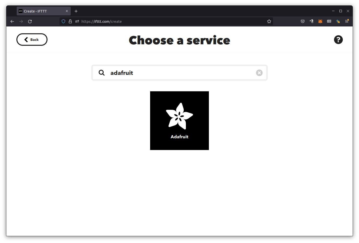
- Click Send data to Adafruit IO

- Connect Adafruit

- Give Adafruit Credentials and Click on SIGN IN

- AuthorizeAdafruit

- Select the feed and enter the value as “1”
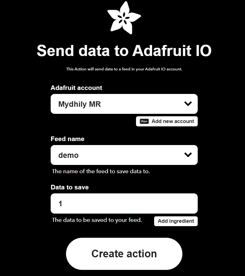
- Click on Continue

- Finish the setup

- The applets you can see in My Applets section

- Now download and install alexa app or any alexa device from play store and configure the app as per the instructions.
Output
When you say the phrase “Alexa Trigger led on” you can see the built-in LED in ARIES board turning ON.
Trigger LED ON
Trigger LED OFF
