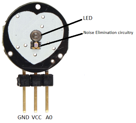
This is all about how to interface Pulse Sensor with ARIES v2 Board to monitor pulse rate. Pulse Sensor is a well-designed plug-and-play heart-rate sensor. The sensor has two sides, on one side the LED is placed alongside an ambient light sensor and on the opposite side, there is a circuitry that is liable for the amplification and noise cancellation work. The LED on the front side of the sensor is placed over a vein in our physical body, onto a fingertip or earlobe, and plugs right into the ARIES v2 Board with the help of jumpers.
Pulse Sensor
The working of the Pulse/Heartbeat sensor is very simple. The LED on the front side of the sensor is placed over a vein in our human body. This can either be your fingertip or your ear tips. Now the LED emitted light will fall on the vein directly. The veins will have blood flow inside them only when the heart is pumping, so if we monitor change in the flow of blood we can monitor the heartbeats.
Circuit Diagram
The Pulse/Heartbeat Sensor Module has three pins: VCC, Analog Out, and GND. Connect VCC and GND of the pulse sensor to +3.3V and GND respectively of ARIES v2 board. Then connect the Analog Out Pin of the Pulse/Heartbeat sensor to the Analog pin A0 of the ARIES v2 Board.
Now, for powering up the ARIES v2 board via USB port of a Laptop/Desktop/PC and burning the code into the ARIES v2 board, we have to use a micro USB type B to USB type A cable. The cable should be connected to UART0 port of the ARIES v2 board, and the Laptop/Desktop/PC should be preinstalled with VEGA SDK and Toolchain.
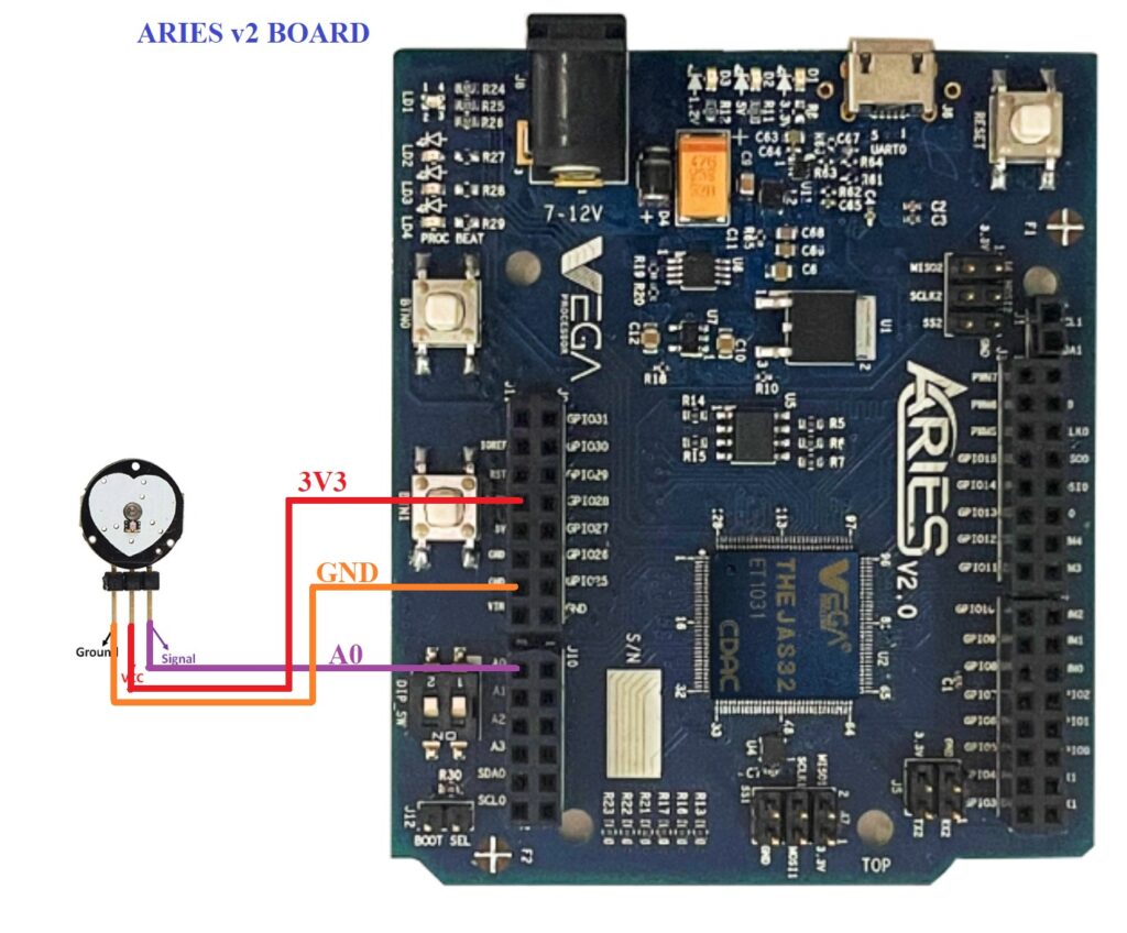
| Pulse Sensor | ARIES v2 Board |
| VCC | +3.3V |
| GND | GND |
| Signal | A0 |
Procedure
After setting up the toolchain and SDK path environments, build the example program for Pulse Sensor by :
cd vega-sdk/examples/adc/pulse_sensor_demomake clean command to clean the executable :
make cleanthen use the make command to build it.
makeNow, we can transfer the built program to the board, before transfer please ensure that you have connected the UART0 connector of the board to the PC.
Open a new terminal and execute the following command.
sudo minicom ariesNow you can see the minicom terminal opened and the board UART terminal is ready.
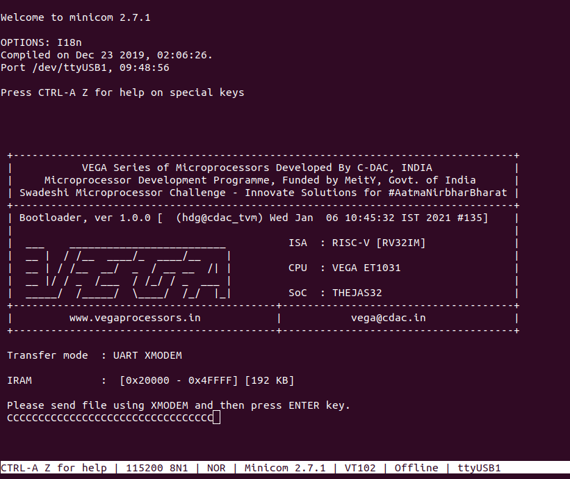
Use CTRL+A S to enter the file sending menu and select xmodem by pressing Enter.
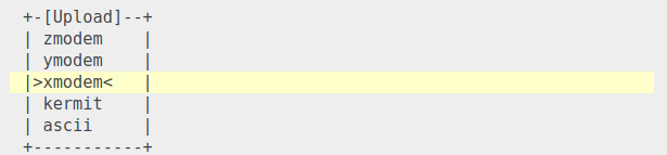
In the next window, with the Space bar select the pulse_sensor_demo.bin file to be transferred, by pressing Enter, the transfer process starts.
Wait until the process is completed. The screen should display how much data has been transferred.
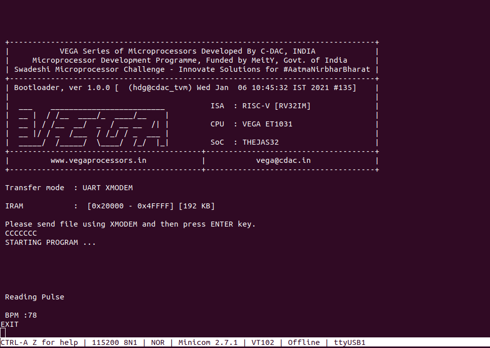
After completing the transfer the Program will start to execute.
Place your finger on the LED side of the sensor. Your pulse rate will be displayed in the minicom UART terminal:
for additional information :