In this tutorial, we are going to control the internal LED in ARIES v3.0 Board from Firebase cloud platform. This tutorial canbe useful if you want to control any objects from cloud server remotely using Wi-Fi.
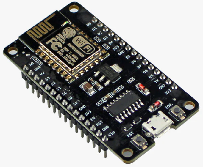
ESP8266 NodeMCU
NodeMCU is an open-source Lua-based firmware and development board specially targeted for IoT-based Applications. It includes firmware that runs on the ESP8266 Wi-Fi SoC from Espressif Systems, and hardware that is based on the ESP-12 module.
ESP8266 is a highly integrated chip designed for the needs of a new connected world. It offers a complete and self-contained Wi-Fi networking solution allowing it to either host the application or to offload all Wi-Fi networking functions from another application processor. Its high degree of on-chip integration allows for minimal external circuitry. It is designed to occupy a minimal PCB area.
Prerequisites
- Windows 10 or above/Linux (64 bit)
- Arduino IDE
- VEGA ARIES Board support package
- NodeMCU Board support package
- Note: Install Version 2.7.4 of NodeMCU board from Tools-> Board Manager for this code to work
Components Required
- ARIES v3.0 Board
- USB type C to USB type A cable
- Micro USB type B to USB type A cable
- NodeMCU module
- Jumper Wires
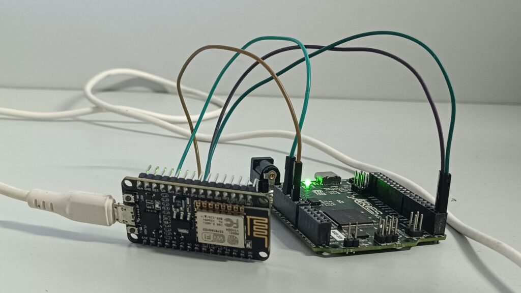
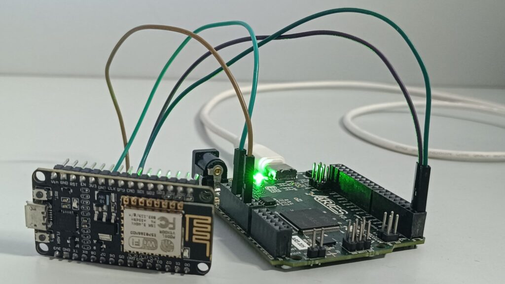
Connection Diagram
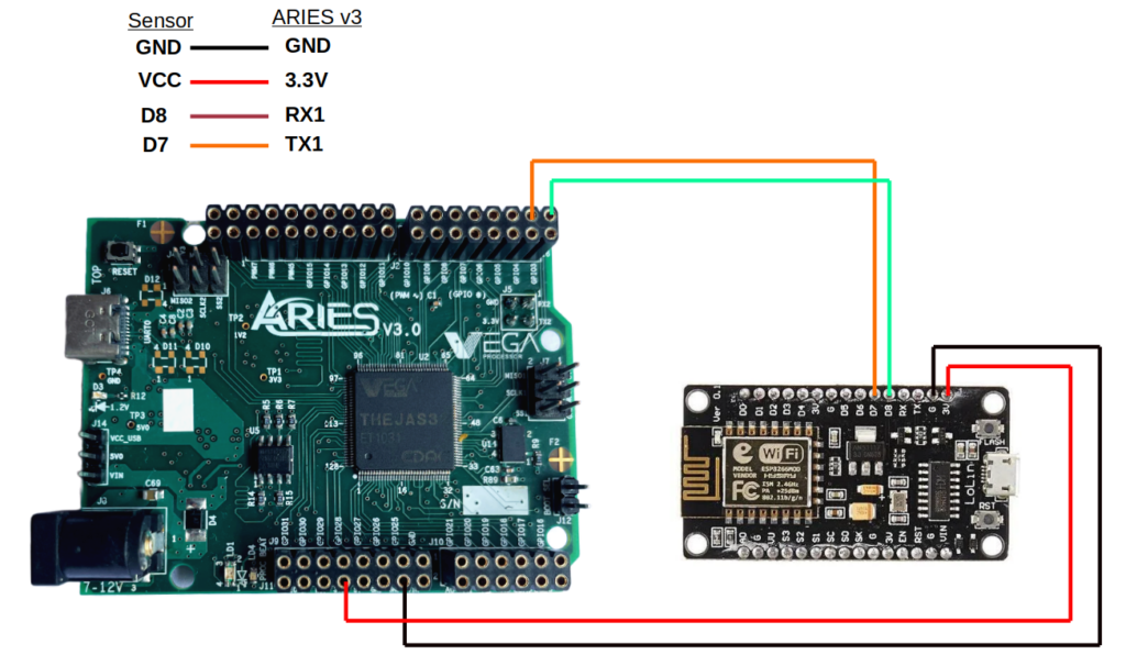
| NodeMCU ESP8266 WiFi Module | ARIES v3 Board |
| VCC | +3V3 |
| GND | GND |
| D7 (RXD) | TX1 |
| D8 (TXD) | RX1 |
Libraries
Arduino libraries are an extension of the standard Arduino API and consists of thousands of libraries, both official and contributed by the community. Libraries simplifies the use of complex codes. Every version of Arduino IDE has a library manager for installing Arduino software libraries. The libraries required for this projects are
- ArduinoJson (Version (5.13.2)
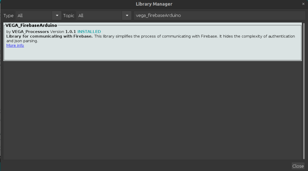
- VEGA_FirebaseArduino (Version 1.0.1)
To install the libraries directly from library manager required for this project.
Go to Tools -> Manage Libraries -> and search with the library names mentioned above
Click on Install

Procedure
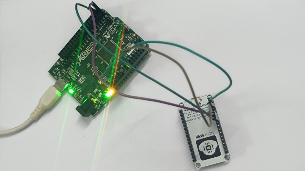
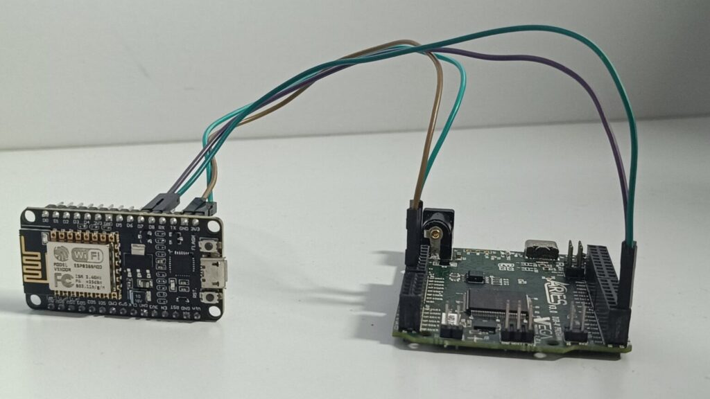
Refer the connection Diagram and connect NodeMCU module to ARIES v3.
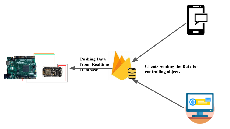
Next we need to configure Firebase cloud by following the below steps:
Steps to do in Firebase cloud platform:
- Visit https://console.firebase.google.com/ and login or create an account if you do not already have.

- click on “Go to Console“

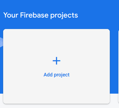
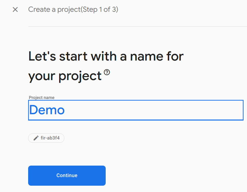
- Click on “Add Project” and give any project name for your project ( Example project name – randomData) and click on Continue
- Click on Continue -> Continue

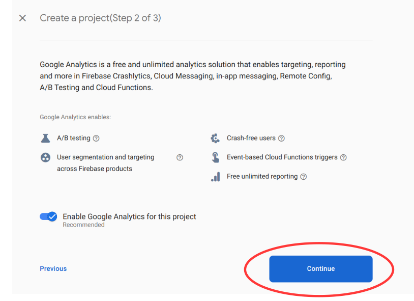
- Select default account for Firebase and Click on “Create Project” and wait for project to be created


- Click on “Continue” and you can see your project created


- Next we need to create the database for our project.
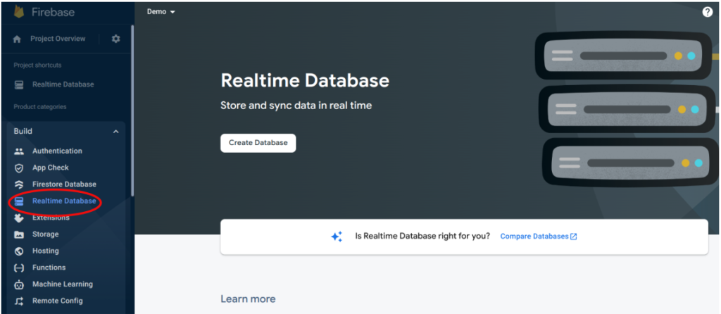
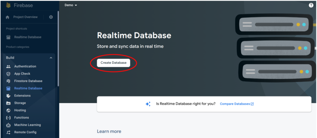
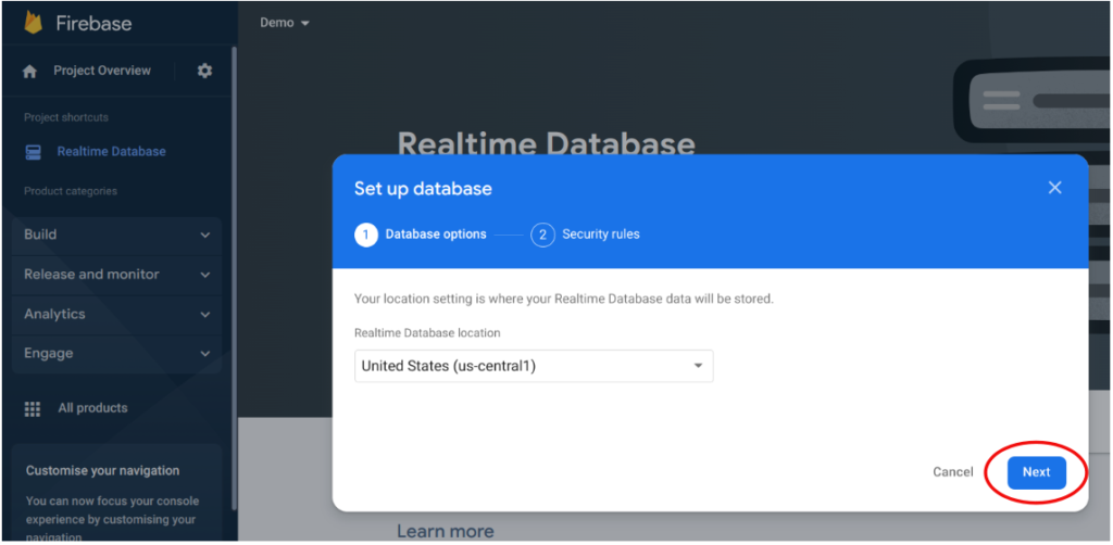
- Click on Build -> Real time Database -> Create Database
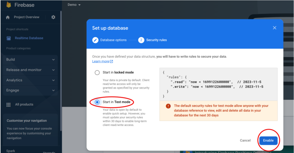
- Click on Next -> Start in Test Mode
- Note: If you selected start in Locked mode then you need to change the rules of database to false for working, after creating the data base.
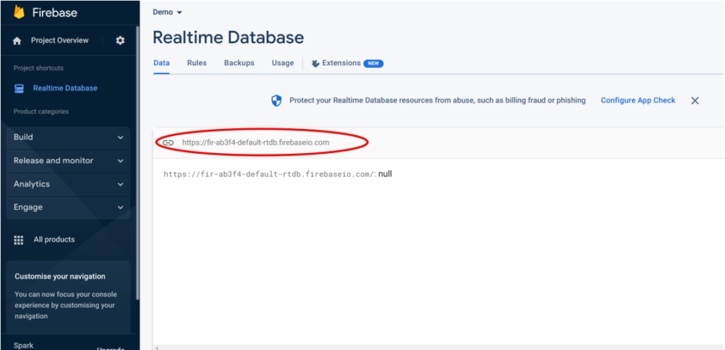
- You can see the url required for this project on the top of your database. Copy this url for future use
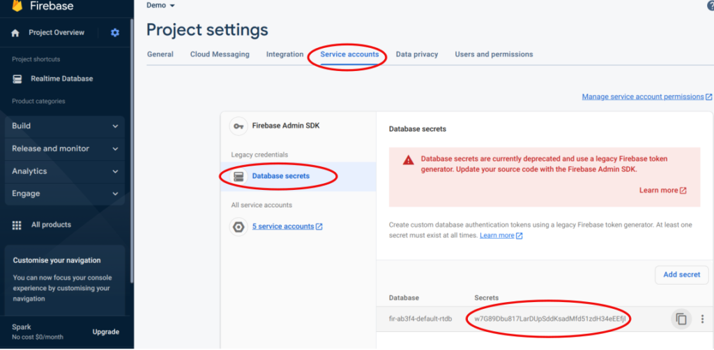
- Go to Project Overview -> Project Settings -> Service accounts -> Database Secrets, to copy the Database key
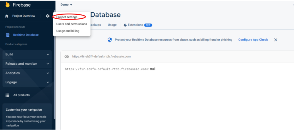
- Click on show and copy the database secret key
- Turn on your mobile hotspot before uploading the code
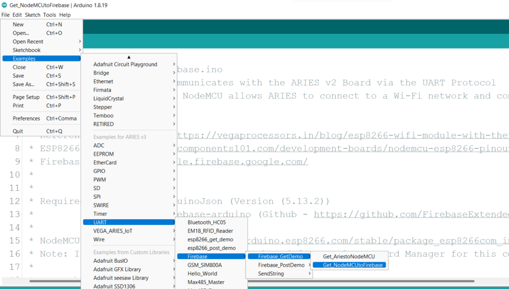
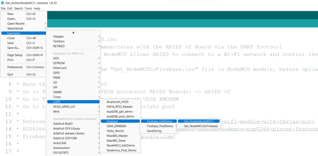
- Now, Open Files -> Examples -> Under Examples for ARIES v3 -> UART-> Firebase -> Get_NodeMCUtoFirebase
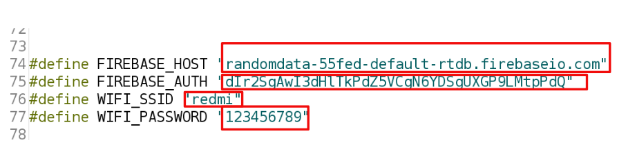
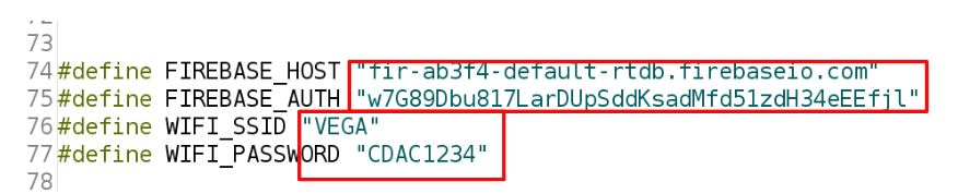
- Change the below settings with your corresponding credentials in the Get_NodeMCUtoFirebase file
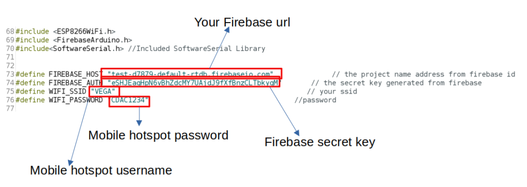
- For the example provided, the settings before and after change is shown in the below figure
Note1:
Don’t forget to remove the “https://” and the last “/” while pasting the url, to get correct output
Note2:
The Firebase Arduino library has a reference to a fingerprint of the Firebase SSL certificate. Sometimes this fingerprint may not match the current fingerprint.This fingerprint is in FirebaseHttpClient.h (typically in Home/Arduino/libraries/firebase-arduino/FirebaseHttpClient.h in Ubuntu).
To find and change the current fingerprint:
- Go to https://www.grc.com/fingerprints.htm
- Enter “test.firebaseio.com”
- Record the fingerprint (e.g. it is currently
6A:7D:A1:11:7F:F3:C2:45:0C:F7:22:E7:A2:35:EA:61:12:55:83:48 - Open Home/Arduino/libraries/firebase-arduino/FirebaseHttpClient.h
- Replace value of
kFirebaseFingerprint[] with the fingerprint (without colons) - Recompile
e.g. the following fingerprint works at this point of time:
static const char kFirebaseFingerprint[] =
  "6A:7D:A1:11:7F:F3:C2:45:0C:F7:22:E7:A2:35:EA:61:12:55:83:48";   //2023-09

For more details refer the following link.- After changing above settings, connect NodeMCU board to your laptop using micro USB type B to USB type A cable.
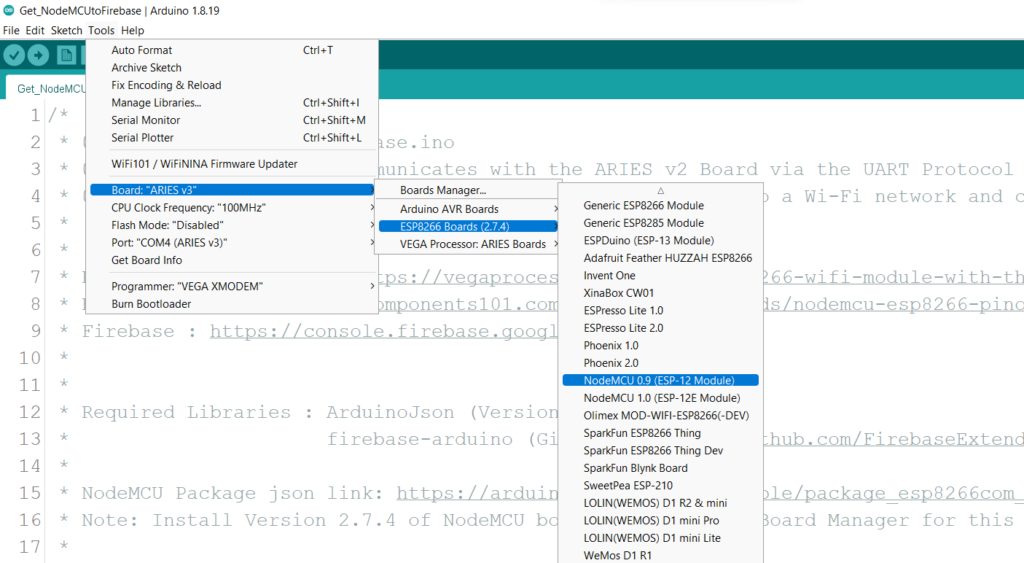
- Go to Tools -> Board -> ESP8266 Boards(2.7.4) -> NodeMCU 0.9 (ESP-12 Module)
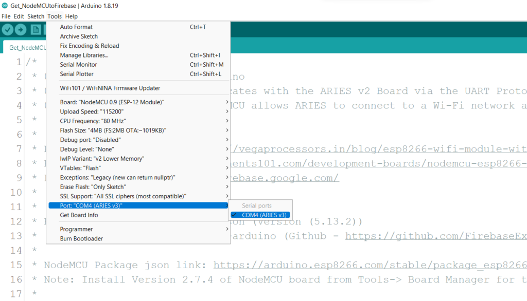
- Go to Tools -> Port -> Select appropriate port
- Now Upload the code to your NodeMCUESP8266 module
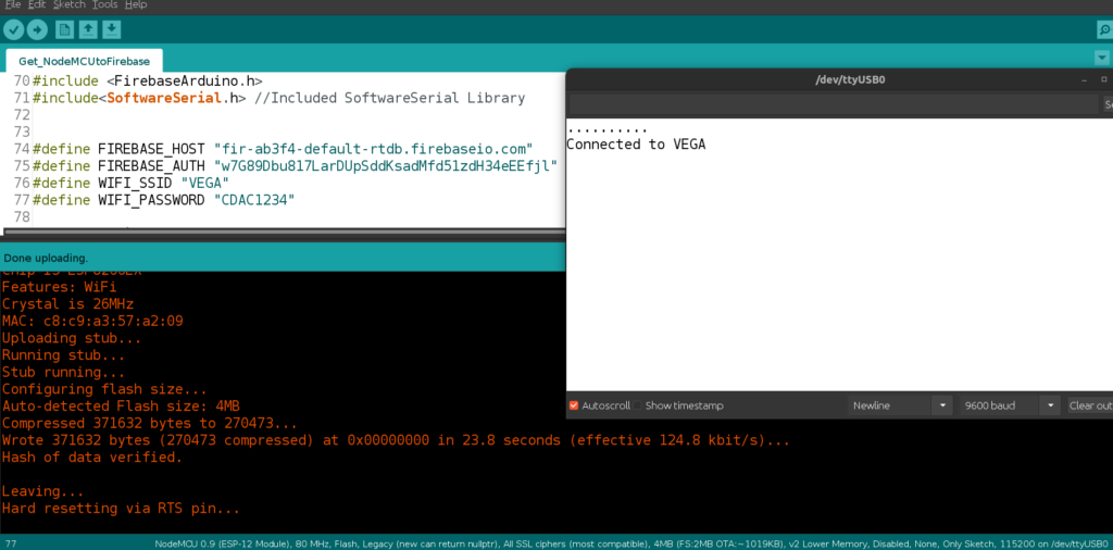
- Open the Serial Monitor in 9600 baud rate, Once the code is uploaded you can see the “Connected to VEGA” message on serial monitor along with status as shown below.
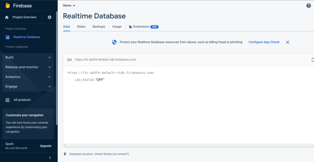
- You can also check the firebase real time database created. if the connection is established properly you can see the below default message printing on the database.
- Now you can disconnect the USB cable from NodeMCU module.
- After disconnecting USB cable from NodeMCU module, follow the below steps to upload code to ARIES v3 board.
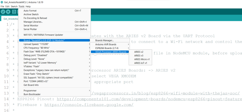
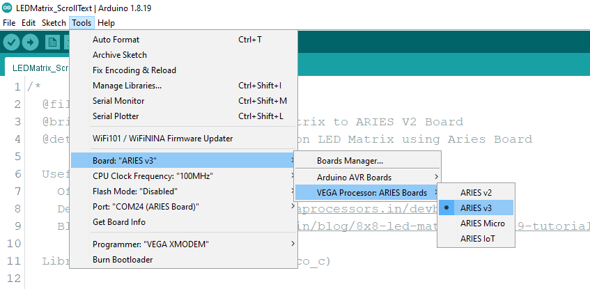
- Go to Tools -> Board -> VEGA Processor ARIES Boards -> Select ARIES v3
- Open Files -> Examples -> Under Examples for ARIES v3 -> UART-> Firebase -> Get_AriestoNodeMCU
Connect Aries board to your computer via the USB port of a Laptop/Desktop/PC. We have to use a USB type C to USB type A cable. The cable should be connected to UART-0 port of the ARIES v3 board, and the Laptop/Desktop/PC should be preinstalled with Arduino IDE and VEGA ARIES boards of latest version.
- After connecting ARIES v3 board to your computer, Make sure you have selected ARIES v3 Board from Tools -> Board -> VEGA Processor: ARIES Boards -> ARIES v3
- Select Programmer as VEGA XMODEM from Tools -> Programmer -> VEGA XMODEM
- Also select appropriate port from Tools -> Port -> COM* (ARIES Board)
- Now upload the code to your ARIES v3 board by clicking on Upload button
Output
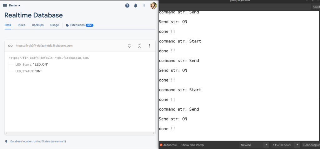
- Once the code is uploded to ARIES v3 board, open the Serial Monitor at 115200 baud rate, and you can see the current status of the internal GREEN LED available in ARIES v3 board on the Serial monitor and in Firebase cloud as shown in the figure below.
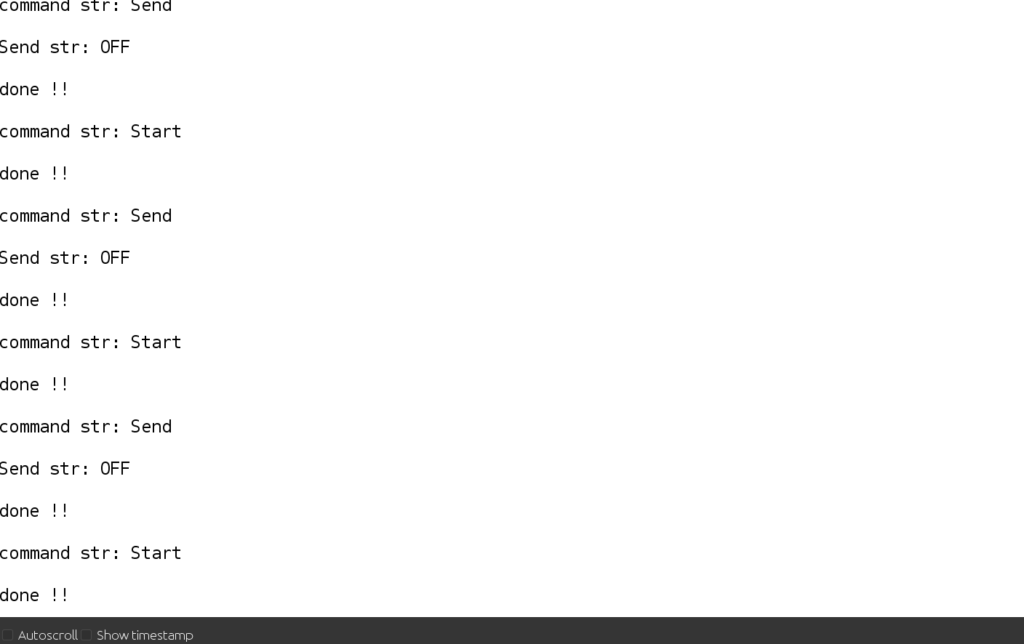
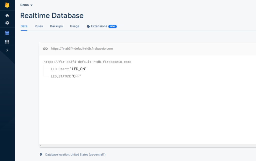
For turning on the internal LED, you can change the LED STATUS (LED_STATUS “OFF“) from OFF to ON. The corrsponding serial monitor display also shows the led status as ON, which helps you to verify the output