In this tutorial we will learn how to use 8×8 LED Matrix to display customize text message with VEGA ARIES Boards. Here we will use Android Application to change text message.
Prerequisites
- Windows 10 or above/Linux (64 bit)
- Arduino IDE
- VEGA ARIES Board support package
Hardware Required
- ARIES v2.0 Board
- MAX7219 Dot Led Matrix Module
- Bluetooth Module HC-05
- Micro USB type B to USB type A cable.
- Jumper wires
Note: All of the following boards can be used for this project
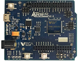
ARIES v2.0 Board
The ARIES v2.0 is a fully indigenous and a “Made in India” product to get started with basic microprocessor programming and embedded systems. This board is built upon a RISC-V ISA compliant VEGA Processor with easy-to-use hardware and software. For more details about ARIES v2.0 boards please refer to the ARIES development boards and Ecosystem.
MAX7219 Dot Led Matrix Module
The MAX7219 are compact, serial input/output common-cathode display drivers that interface microprocessors (µPs) to 7-segment numeric LED displays of up to 8 digits, bar-graph displays, or 64 individual LEDs.
Bluetooth Module HC-05
The HC-05 is a class 2 Bluetooth module designed for transparent wireless serial communication. It is pre-configured as a slave Bluetooth device. Once it is paired to a master Bluetooth device such as PC, smart phones and tablet, its operation becomes transparent to the user. All data received through the serial input is immediately transmitted over the air. When the module receives wireless data, it is sent out through the serial interface exactly at it is received.
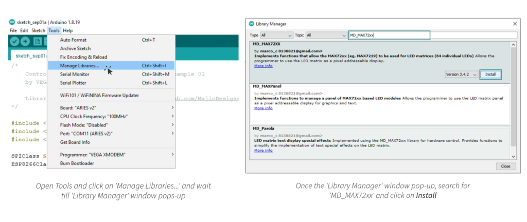
Libraries Required
Download the MD_MAX72XX Library from Tools >> Manage Libraries…
Circuit Diagram
Now let’s connect the 8×8 LED Matrix module and HC-05 Bluetooth module to the ARIES v2 board.
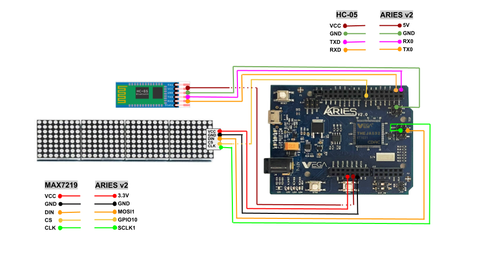
Connections
| MAX7219 LED MATRIX | ARIES V2.0 Board |
| VCC | 3.3V |
| GND | GND |
| DIN | MOSI-1 |
| CS | GPIO-10 |
| CLK | SCLK-1 |
| Bluetooth Module HC-05 | ARIES V2.0 Board |
| VCC | 5V |
| GND | GND |
| TXD | RX-1 |
| RXD | TX-1 |
Arduino Code
Once we are done with the connections we are ready to take a look at the Arduino code.
/*
    Controlling 8×8 LED Matrix via Bluetooth Example 01
    by VEGA Processors, www.vegaprocessors.in

    Library Required: MD_MAX72xx [https://github.com/MajicDesigns/MD_MAX72XX]
*/

#include <SPI.h>
#include <MD_MAX72xx.h>
#include <esp8266.h>

SPIClass SPI(1);
ESP8266Class Bluetooth(1);

// Define the number of devices we have in the chain and the hardware interface
#define HARDWARE_TYPE MD_MAX72XX::FC16_HW
#define MAX_DEVICES 4
#define CS_PIN    10  // connect CS pin to GPIO-10
/* NOTE: You can use any GPIO Pin from the board */

MD_MAX72XX mx = MD_MAX72XX(HARDWARE_TYPE, CS_PIN, MAX_DEVICES);

char stringBuffer[1000] = {0, };
int count;

#define  DELAYTIME  100  // in milliseconds

void scrollText(const char *p)
{
  uint8_t charWidth;
  uint8_t cBuf[8];  // this should be ok for all built-in fonts

  mx.clear();

  while (*p != '\0')
  {
    charWidth = mx.getChar(*p++, sizeof(cBuf) / sizeof(cBuf[0]), cBuf);

    for (uint8_t i=0; i<=charWidth; i++)  // allow space between characters
    {
      mx.transform(MD_MAX72XX::TSL);
      if (i < charWidth)
        mx.setColumn(0, cBuf[i]);
      delay(DELAYTIME);
    }
  }
}

void setup() {
  // Open serial communications and wait for port to open:
  delay(1000);
  Serial.begin(115200);
  Bluetooth.begin(9600);
  while (!Serial) {
    ; // wait for serial port to connect. Needed for native USB port only
  }
  mx.begin();
}

void loop() {
  count = 0;
  for(;count<1000;count++){
    stringBuffer[count] = 0;
  }
  Serial.print("Ready to receive text....");
  while(1){
    count = 0;
    while(Bluetooth.available() > 0){
      stringBuffer[count++] = Bluetooth.read();
    }
    if(stringBuffer[count-1] == '\n'){
      stringBuffer[count-1] = '\0';
      break;
    }
  }
  Serial.println("received.");
  count = 0;
  for(;count<1000;count++){
    Serial.print(stringBuffer[count]);
  }
  Serial.println();

  while(1){
    scrollText(stringBuffer);
    if(Bluetooth.available() > 0){
      uint8_t newText = Bluetooth.read();
      if(newText == 'N')break;
    }
  }
}
Procedure
Let’s power up the board. Make sure the Laptop/Desktop/PC which we’re using should be preinstalled with Arduino IDE and VEGA ARIES Boards of latest version.
- Now, Open the Arduino IDE
- Create a new Sketch File -> New
- Copy-paste the above Arduino code to it.
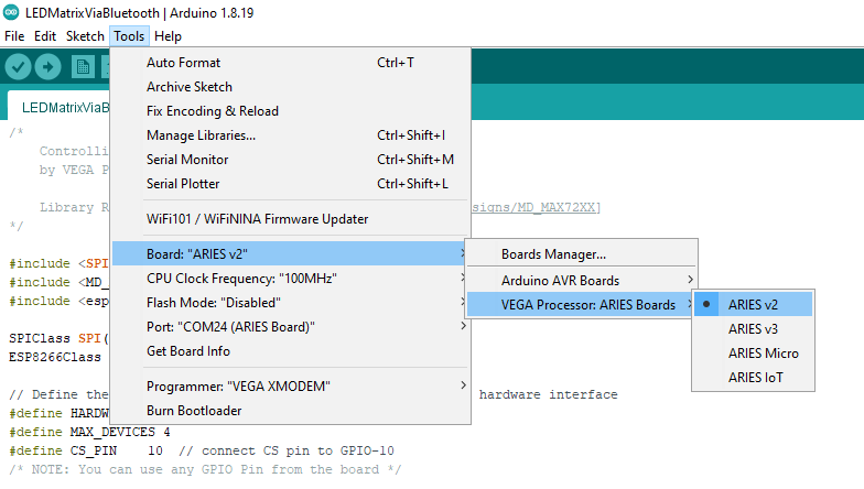
- Make sure you have selected ARIES v2 Board from Tools -> Board -> VEGA Processor: ARIES Boards -> ARIES v2
- Select Programmer as VEGA XMODEM from Tools -> Programmer -> VEGA XMODEM
- Also select appropriate port, Tools -> Port -> COM* (ARIES Board)
- Now, Upload the sketch in ARIES v2 board and open the serial monitor at 115200 baud rate.
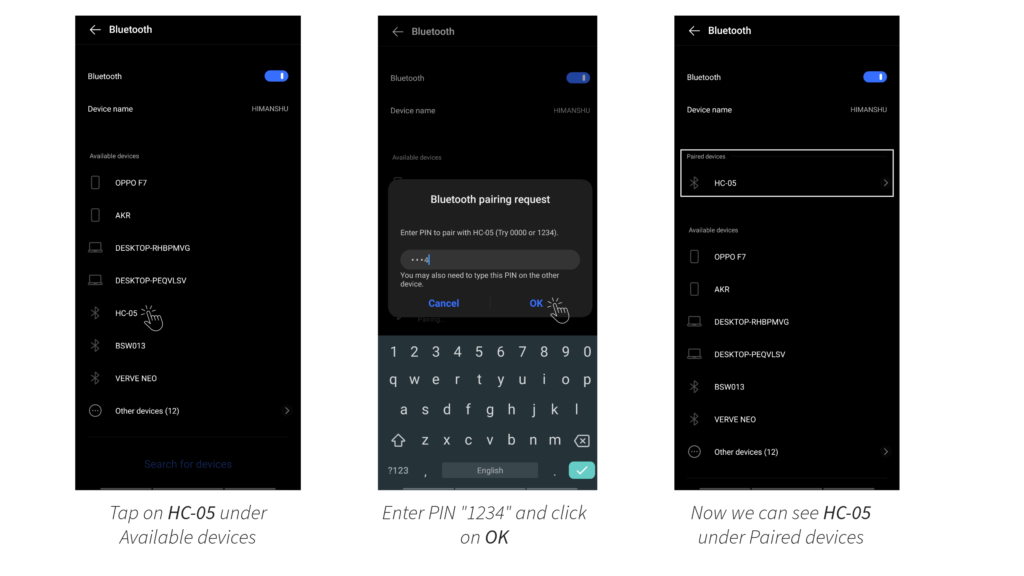
- On your Android phone, turn on the bluetooth. Search and tap on HC-05 in Available devices. Enter pin as “1234” and click on OK. Now you can see HC-05 under Paired devices.
- Now open Custom Display App in your phone. Click on BLUETOOTH button, select HC-05 and wait till it get connected.
- Enter any text in text box and press on SEND button.
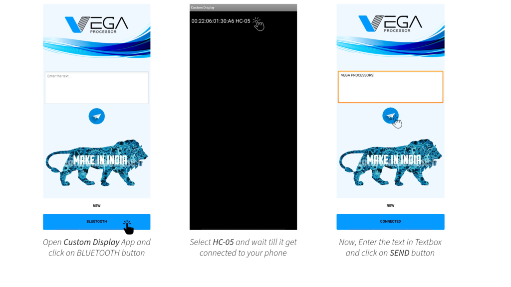
- Finally you can see the text you have send from the Android app scrolling on your LED Matrix. To change the text message, click on NEW button, re-enter the text in text box and press SEND.
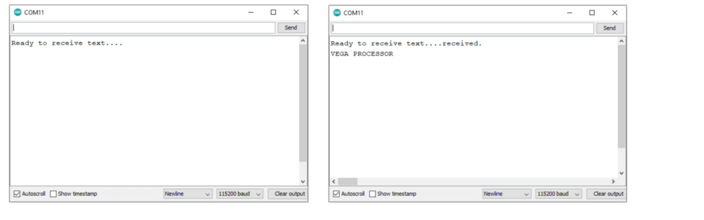
Output
When the code is uploaded, Ready to receive text…. will display on serial monitor. Once it did, send a text message from the Custom Display app. Now, the same text message will display on LED Matrix as well as on serial monitor. To change the text message, click on NEW button on an app and wait till the text message scrolling on LED Matrix stops. Now re-send the new text message.